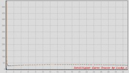
Temperature controlled curve tracing
Hi,
wanted to measure my transistors at operating temperature of my class-A amp. I found a way to do this and thought I share it here. May it be useful for others 😀
Pictures speak for themselves....
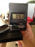
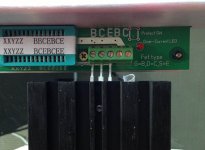
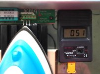
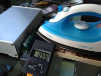
You need:
- An aluminum strip, and transistor (isolated) attached to it.
- Digital thermometer attached to aluminum strip (probe close to transistor)
- electric iron (or similar)
What needs to be determined:
I noticed from other temp measurements in real amps- where the transistors are heating up the heat sinks: When heat sinks have 50 Degree Celsius, the transistors can have 70-80 Degrees Celsius.
If you are heating the heat sinks, to simulate such temperatures of transistors, you need to take that into account.
-Oliver
Hi,
wanted to measure my transistors at operating temperature of my class-A amp. I found a way to do this and thought I share it here. May it be useful for others 😀
Pictures speak for themselves....


You need:
- An aluminum strip, and transistor (isolated) attached to it.
- Digital thermometer attached to aluminum strip (probe close to transistor)
- electric iron (or similar)
What needs to be determined:
I noticed from other temp measurements in real amps- where the transistors are heating up the heat sinks: When heat sinks have 50 Degree Celsius, the transistors can have 70-80 Degrees Celsius.
If you are heating the heat sinks, to simulate such temperatures of transistors, you need to take that into account.
-Oliver
Last edited:
I suggest use PTC heating a small aluminum,
The PTC is constant temperature. it can be detached from the 'USB Tea Coffee Cup Warmer Heating Pad'.
The PTC is constant temperature. it can be detached from the 'USB Tea Coffee Cup Warmer Heating Pad'.
Hi, Locky. My tracer stopped working. I used it last time 2 years ago - everything was right. Now turn on the JFET, load old preset, click start... Relay clicks once on and off, and on only one point of the curve with coordinates 0,I(0). What shall I do?
In the yahoo group, I had put the newest hardware and trouble manual.
Follow the section "Curve Tracer Diagnosis" to check.
Follow the section "Curve Tracer Diagnosis" to check.
Thanks, Locky. I have checked, all works as described in "Curve Tracer Diagnostic". But I can't measure anything...
1.Select menu 'measurement->curve tracer'
2.Checked the 'Calibration before measure'
3.Click the button 'offset test'
You can 4 curve tracer. Normaly their vertical max will between -0.005 ~ +0.005. If not, maybe calibration relay or OP07 not good.
2.Checked the 'Calibration before measure'
3.Click the button 'offset test'
You can 4 curve tracer. Normaly their vertical max will between -0.005 ~ +0.005. If not, maybe calibration relay or OP07 not good.
With unplugged inputs:
Code:
    VE    VBE
1    4.11860179901123    -0.0529229268431664
Code:
    VE    VCE
1    4.11860179901123    -0.0503344722092152
Code:
    VE    VRB
1    4.11860179901123    -0.0326614305377007
Code:
    VE    VRC
1 4.11860179901123 -0.00141379528213292When click the button 'offset test', only a row data ?
Normaly, click the button, the system will short VRB/VRC/VBE/VCE ADC channel to E channel output, and control E channel output from 2.5 to 36V, and measure the the relationship VRB/VRC/VBE/VCE between VE. So you will get 4 table and every table have about 60 rows data.
Normaly, click the button, the system will short VRB/VRC/VBE/VCE ADC channel to E channel output, and control E channel output from 2.5 to 36V, and measure the the relationship VRB/VRC/VBE/VCE between VE. So you will get 4 table and every table have about 60 rows data.
Yes, that's what I say! Relay is switched once, then measurement stops, and the graph has a single point. So in all modes. DUT test works correctly.When click the button 'offset test', only a row data ?
Maybe E channel output have wrong.
Follow the section "5.Check the power amplifier output OK?" in hardware pdf, Set E channel output and compare the voltage of measured by multilmeter test socket E.
Follow the section "5.Check the power amplifier output OK?" in hardware pdf, Set E channel output and compare the voltage of measured by multilmeter test socket E.
Hello, Locky.
Just got time to solve the problem. Tested all three channels, the error voltage less than 10%but generally, voltage control works.
And then I remembered about the symbol of separation. In regional settings again was "," instead of "." Necessary to fix this bug, the second time get on the trap.
Just got time to solve the problem. Tested all three channels, the error voltage less than 10%but generally, voltage control works.
And then I remembered about the symbol of separation. In regional settings again was "," instead of "." Necessary to fix this bug, the second time get on the trap.
Last edited:
Measurement of hfe-ic curve, At the begin section have some a great value.
Becauserthe initial value of VB is too small, the Ib and Ic also small, then measure the voltage on RB/RC accuracy is poor, and hfe=Ic/Ib will change greatly.
To solve this , set the begin value of VB bigger.
In some Latin language windows the decimal separator is ',' not '.' , so the windows read the float value from ads7871_v3s.INI file will have some wrong.
But this not solves idle B offset. Can I calibrate this?To solve this , set the begin value of VB bigger.
In Russian separator is ",", so your program needs some adjustment, but for others needs ",". Why not make a fixed separator for all, and in the edit box to adjust for it?In some Latin language windows the decimal separator is ',' not '.' , so the windows read the float value from ads7871_v3s.INI file will have some wrong.
When you load P-type , system will do some step
1. Get the maxim voltage output, example is 36V
2. Set E channel output 36V- Vdrop, Vdrop is the 'Voltage Drop(source)' parameter in system config,example is 1.5V, so E channel set to output 34.5V.
3. if you set Vb from -0.1V to -6V, it mean B chanel will output less than E channel 0.1Vto 6V, so system will set B channel output 34.4V to 28.5V
But the different channel consistency is not guaranteed. so system set B output 34.4V but the real voltage may be 34.7V or 34.2V. So the difference between the B/E channel is not what you set 0.1V.
The reason is:
The high bit DAC in curve tracer is combined by two 8bit DAC, it can only produce voltage monotonically and increasing, but the linear is not good. And the different channel consistency is not guaranteed.
About the separator, system read the float parameter from ini file, the function provided by the microfoft windows.
- Home
- Vendor's Bazaar
- Intelligent Curve Tracer 3.0 release
