My Direct Coupled inspired by Dr Lowmu
Might cost an arm and a leg with all those bypass caps.....
So don't use them. The concept is rather senseless. Use a good, high quality bypass and avoid potential issues with unintended resonances at HF.
Do a quick calculation: what's the "looking in" impedance at each of the cathodes?
My Direct Coupled inspired by Dr Lowmu
Might cost an arm and a leg with all those bypass caps.....
Does a 12ax7 had the stones to drive 2a3? - even when parallelled? You might just want to try a pentode or triode strapped pentode... then LED bias the first stage...
Do a quick calculation: what's the "looking in" impedance at each of the cathodes?
You lost me there. Are we calculating impedance of the parallel caps and resistors at a given frequency? Or each one separate at different frequencies?
I see your point as each one would behave differently at the same frequency.
Does a 12ax7 had the stones to drive 2a3? - even when parallelled? You might just want to try a pentode or triode strapped pentode... then LED bias the first stage...
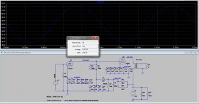
Doesn't do a great job but the MU is very high on the 12ax7. Anything past 2.5 watts and it starts falling apart. If your looking for the output of a 45 in a two stage then this would make sense.
The attached is a snap shot of the voltage swing at the 12AX7
Attachments
Last edited:
My Direct Coupled inspired by Dr Lowmu
Might cost an arm and a leg with all those bypass caps.....
I sorta LIKE your post !!
You want R1 to be 250K or more, not 100K.
You do NOT understand how we bypass Rks. Never ever ever by traditional formula, always determined carefully by ear.
The largest Rk cap ( main cap ) on the 12AX7 will be 15 uF Film. All the other bypass caps, to that, will be various diminishing uF sizes, all under 1 uF, selected by ear, usually 5 added. Ditto for the 2A3 Rk, except 10 uF would be the largest main cap. The B+ voltages you picked are right on, very good.
If you wanna build something, I think you should contact me privately so you get it done well. I will help.
Jeff Medwin
Does a 12ax7 had the stones to drive 2a3? - even when parallelled? You might just want to try a pentode or triode strapped pentode... then LED bias the first stage...
Half a 12AX7 will easily drive a 2A3 or Type 45 grid, because the 2A3 and Type 45 is EASY EASY EASY to drive in a direct couple !!!
Never should you try to parallel the driver tube, because, being high mu ( 100 ) you will get poorer sound, due to skewing of two dissimilar 12AX7 sections. Diction and enunciation on voice will clearly suffer, despite the "technical " EE reasons to parallel, it doesn't ever work.
Isamu Asano used 0.43 mA. and I use 0.60 mA. to drive the 2A3 superbly. Nobukazu Shishido used 1.0 mA. to direct drive the 2A3, but I have a feeling, Nobu's published schematic on line is NOT what he did in real life, a single triode is what sounds best there, Nobu showed us a paralleled 12AX7- yuck !!
I have A-Bed all of this, as have others, and I have DIRECT experience.
I 'wanna understand ALL the words, inflection, and intent, when I listen to Gilbert and Sullivan Savoy Operas !!! One will not be able to improve upon half a 12AX7. Amazing isn't that !! But very true from all of my years experimenting with Loftin-White 2A3 amps!!
Jeff Medwin
Doesn't do a great job but the MU is very high on the 12ax7. Anything past 2.5 watts and it starts falling apart.
Please NOTE :
On proper high efficiency speakers, ALTEC, JBL, ALE, etc, we operate the amp under 1 watt almost all the time, and so, we want to make the first 1/10th to 3/4s of a Watt superb, right where we play the amp 99% of the time !!!
Think in terms of building "World's Best" under 1 Watt amp, that can do 3.5 Watts, if called upon to do so momentarily.
Jeff Medwin
You lost me there. Are we calculating impedance of the parallel caps and resistors at a given frequency? Or each one separate at different frequencies?
Neither. Multiple parallel caps are generally not useful and can sometimes cause problems of their own. The question then is, what to use for bypassing.
You start by determining the impedance that you need to bypass. For example, let's look at the first stage. The effective impedance at the cathode is 3k (the two paralleled cathode resistors- you really only need one resistor there, paralleling has no advantage) in parallel with the plate load + plate resistance divided by the mu. In this case, the plate load is 300k (the two 600k paralleled, ditto the previous comment), plate resistance is about 70k, mu is 100. So in parallel with the cathode resistor, you have (300 + 70)k/100 = 3.7k. In parallel with the 3k, you have an impedance at the cathode of about 1.7k. That's what needs to be bypassed.
Let's calculate the required capacitance. We'll call the lowest frequency of interest (say, a decade below the desired bandwidth) 2 Hz. For an f3 (at the cathode!) of 2 Hz, the capacitance calculates as C = 1/2pifZ = 1/(6.28)(2)(1700) = 47uF. So use a 47uF electrolytic cap there. You might want to go a bit smaller on it since there's a tradeoff between low frequency response and overload recovery time. But let's go with 47u for illustration.
An aluminum electrolytic cap will have a small ESR (under 0.1 ohm), but above its self-resonant frequency, the impedance starts to rise. For a single good quality cap (i.e., NOT an "audiophile" capacitor, but a well-manufactured name brand part), that rise might be as high as 3 or 4 ohms at 500kHz, way past any bandwidth you care about. But notice that the impedance is ridiculously low compared to the impedance at the cathode (1700 ohms). So the bypassing quality does not significantly change for any audio frequency and for at least an order of magnitude beyond.
Multiple bypassing complicated the picture by adding in all sorts or stray resistances and inductances. At best, it won't make things any worse than using a single decent bypass cap. At worst, you'll compromise the circuit stability because of the strays and the new loops created by the physical placement and wire leads.
Hello Sy,
You and I both mean well, but your advice is almost 100% different than mine. DeafbyKhorns is talking in this thread about building a "LowMu inspired" amp. That is me, not you dear sir !! In many design areas, above, you are telling him just the opposite of how I would build the 2A3 DC amp.
In your entry quoted above, well, ...... 'changed my mind - I don't think I want to get into differences in design approach and philosophy with you. Let me just say, you and I have large differences on how to approach such a DC 2A3 Amplifier build.
Both of us can not contribute by advising DeathbyKhorns in this thread. I can not spend time rebutting conventional EE wisdom, and be aware, I have developed a parallel but different approach, with different sensibilities, than you have been trained to do all your life.
I will therefore drop out of participating this thread. DeathbyKhorns, if you want to contact me privately, my email address is drlowmu@gmail.com, and I would be very pleased and happy to work out details of any such design as we have been discussing herein. We will just do it privately, might be a LOT easier that way. Or, you can follow Sy explicitly, but you can't do both, or "pick and choose" parts of each of us, in one build. Cheers to everyone !!
Jeff Medwin
I can not spend time rebutting conventional EE wisdom...
Indeed, if you think that such things as basic tube operation, Ohm's Law, Kirchoff's Law, and Maxwell's equations are "conventional EE wisdom." If you have data or analysis showing superior performance by ignoring these things, I'd certainly be interested in hearing about it.
Surely the pin-socket contact itself is far worse than any solder joint? If we can't use solder, and we can't use sockets, should we go back to using brass blocks with screws for audio wiring?drlowmu said:Where the 6SL7, or ANY high mu octal tube "messes up", is when they have to add an extra solder joint, on every pin of the octal socket, which causes its vagueness in sound - as a high mu driver.
Despite all EE theory, a 'partial' bypass actually does what theory says it should. Adjusting by ear is merely 'bass tone control by soldering iron' - or is it 'bass tone control by screwdriver' (see above)? Putting different low-loss caps in parallel is asking for resonance problems. If you get an accidental parallel resonance here it will create a frequency notch. More tone control?d) One other thing, despite all E.E. theory, use a film cap on the Final's Rk, and make it act as a partial Rk bypass, to YOUR ear !! I usually use 8 uF to 10 uF as a main Rk bypass cap, with smaller value ( < 1 uF ) film caps in parallel. Have fun.
A power transformer and a choke are astonishingly similar, so by no useful definition of words could one be described as "very active" and the other as "passive".There is a HUGE difference between the effects of a Power Transformer, Rectifier, and a Choke. The first two are very active devices, whereas the choke is a passive and DRIVEN member of the trio.
Chokes store energy. That is how they oppose changes in current flow. It may be that you are describing, in a round about way, problems arising from subsonic PSU resonances. Why not say so? These resonances may be affected by the rectifier type used, as a tube rectifier may impose different damping from SS - in effect you get a softer clamping action, but for a greater fraction of time.It NEEDS to be low in DCR and in mass , to be driven easily, AND, to not exhibit too much stored energy which gets released out-of-time to the music.
Surely the pin-socket contact itself is far worse than any solder joint? If we can't use solder, and we can't use sockets, should we go back to using brass blocks with screws for audio wiring?
Despite all EE theory, a 'partial' bypass actually does what theory says it should. Adjusting by ear is merely 'bass tone control by soldering iron' - or is it 'bass tone control by screwdriver' (see above)? Putting different low-loss caps in parallel is asking for resonance problems. If you get an accidental parallel resonance here it will create a frequency notch. More tone control?
A power transformer and a choke are astonishingly similar, so by no useful definition of words could one be described as "very active" and the other as "passive".
Chokes store energy. That is how they oppose changes in current flow. It may be that you are describing, in a round about way, problems arising from subsonic PSU resonances. Why not say so? These resonances may be affected by the rectifier type used, as a tube rectifier may impose different damping from SS - in effect you get a softer clamping action, but for a greater fraction of time.
Your points and responses, every one of them, is opposite of what I find in real life, actual practice.
You should design and build exactly the way it pleases you, and vice-versa for me and my builds !!
Best wishes to and for you, and good luck in your builds.
Jeff Medwin
This is amazing - we appear to have a visitor from another dimension, where the laws of physics are different from here. Should I phone NASA or the United Nations? What is the protocol for such an encounter?
This is amazing - we appear to have a visitor from another dimension, where the laws of physics are different from here. Should I phone NASA or the United Nations? What is the protocol for such an encounter?
Jeff your posts are not in the spirit of diyAudio where knowledge is shared openly and not in secretive little dollops, so I am going to ask you nicely once to stop promoting your friend's designs here if you are not free to disclose this publicly to our membership.
Its seems drlowmu getting tired flooding just one forum (audioasylum) with junk science.
For anyone who is not aware yet, there are 2 fellows on audioasylum.
tube wrangler, totally incompetent tweaker, a decent builder, and a good marketeer with pitiful attempts to present himself as an expert with typical audiophile fog and dust; and his "student" - drlowmu.
Since drlowmu is too shy to present his "ideas", I'll do a favor for diyaudio crowd in order to enlighten them with straight path to the bright future of audio engineering and science.
tube wrangler said:Not all hum is alike-- like everything else, it has its own internal components.
A "little bit" seems to aid both interconnects and speaker cables, keeping a bias signal on them so that they really respond quickly to musical transients-- capture the "leading edge" as musicians say.
tube wrangler said:Everything you're saying here is true, BUT-- and here's the rub-- ALL capacitors are VERY flawed devices. And I do mean ALL of them.
The problem isn't "tuning" or NOT "tuning" to one's tastes by rolling capacitors, I understand that that's what a lot of people do, and I don't argue with their choices-- but to me, that's never been the issue.
Rather, the issue is-- how can we get this piece of man-made parts (an amplifier) to accurately follow the signal that is given it-- in ALL RESPECTS-- including musical timing issues. After all, musical events are pulses, so the pulse behavior of an amplifier, handling multiple differing pulses-- all at the same time-- is relevant..
The question for an audio circuit is-- what is it going to do TO those pulses? How is it going to modify/change them-- IT ALWAYS WILL--, so what can one do to preserve as much of the original signal's integrity-- which is always a set of multiples-- as possible?
Better yet, how will one know that the output signal is correctly tracking the signal input, when 98% of what we can measure doesn't necessarily translate into actual performance on the job (musical integrity as a whole)?
People try to measure all of that. But they can't. We can only measure the parts that we are aware of, and that engineers have designed test equipment for. The rest could be called "voodoo"-- it is by some, but that doesn't answer the question, does it? The question is-- how can we preserve ALL of the signal's MUSICAL qualities?
drlowmu said:What is sorely missing from this conversation is that different uF values of caps, play different parts of the sonic spectrum.
With conventional high quality film caps, it takes SEVERAL different caps to get the entire music presentation displayed evenly to our ears.
Caps may measure wide band statically, but they play terribly narrow band in reality.
drlowmu said:You are not thinking very clearly about audio design and the transfer of energy through a system.
An inch of bad wire can ruin the musical experience.
drlowmu said:I much prefer the sound of NO thermistor on my low DCR B+ supplies. I much prefer the sound of NO AC safety fuse in my own built / wired audio gear.
drlowmu said:The amps [from Serious Stereo / tube wrangler] have been laboratory tested Triode Kingdom.
Dennis [tube wrangler] took them to the University and they all had a GREAT time testing them. They test very well, in Frequency response, THD, any relevant test you wanna throw at them.
At Dennis' discretion, he chooses not to make that information public. He wants people to judge the amps by the ONLY thing that matters, (1) ARE THEY RELIABLE AND (2) How DO THEY actually sound.
Let's leave arguments at other forums at other forums. We have plenty enough of our own here! 😀
Data, evidence, analysis- it's either there or it's not. If it's there, we can discuss it. If it's not, we can dismiss it. Fair enough?
Data, evidence, analysis- it's either there or it's not. If it's there, we can discuss it. If it's not, we can dismiss it. Fair enough?
"Let's leave arguments at other forums at other forums. We have plenty enough of our own here! "
I totally agree, there is no need for heated or negative arguments here.
I do feel we need to be open minded enough to listen to the Serious stereo SE 2A3 amp and system at audio shows in order to properly evaluate the outcome of its design.
I do NOT think everything about music reproduction with electrical means is about measurements. Even though there is some basis for believing they do.
I say let your ears be a part of the decision if it sounds good or not.
NW
Disclaimer: I have NO vested interest in Serious Stereo other than I have heard this system and think it sounds as good as anything I have heard in my 40 years of listening to stereo reproduction through electrical means. Of course there are flaws to any system. But in my opinion this systems gets you very close to the music.
Last edited:
I do feel we need to be open minded enough to listen to the Serious stereo SE 2A3 amp and system at audio shows in order to properly evaluate the outcome of its design.
It's always useful to evaluate electronics in unfamiliar systems sited in unfamiliar rooms, generally playing unfamiliar material.
This is amazing - we appear to have a visitor from another dimension, where the laws of physics are different from here.
This visitor has been around for a long time except he usually resides in another forum/planet. He has a history. Nothing he posted is about "discussion." It's always about doing it his way, which is fine if they are his amps. But he wants everyone to do it his way or they're wrong. It's like arguing with the Linnies.
"Let's leave arguments at other forums at other forums. We have plenty enough of our own here! "
I totally agree, there is no need for heated or negative arguments here.
How about to get over 8500 posts here from drlowmu, all about this infamous low DCR power supply, "musical" one inch wire and a great "inventor" from Serious Stereo (just for fun do a search on audioasylum)?
Thread started by goldenbeer was really interesting until members with real knowledge of electronics have to debunk junk science rather discussing pros and cons of different designs. Garbage posts eating screen real estate, they are boring to scroll, after all its abuse of freedom of speech.
Sorry for the off-topic loud rant. I know 3 electronic forums, sometime ago quite good, which have eventually dried and degenerated because of few domestic flooders,
I don't want diyaudio to become next one.
Spam plague must be stopped from the beginning.
hey Jeff - many thanks for all the help back in the day on my 5842Q/2a3 transformer coupled amp. I had a whole cook book with tips from you, Ed Warden, Bill Petrowsky and Christopher Paul - think it got ditched during a cleaning - wish I could gather the info again.

- Status
- Not open for further replies.
- Home
- Amplifiers
- Tubes / Valves
- 3 direct coupled 2A3 amps