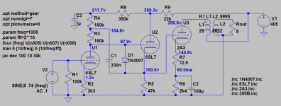
I spiced up the cathode follower circuit (3rd schematic post #1) a little. The freewheeling diode protects the 6SL7 during power on. The pre-stages deliver a nice 90 Vpp at 2ma thru the 2nd 6SL7 into the 2A3. Input sensitivity is 0.5V RMS.
THD for the pre-stages at full power is <0.1, with H3 and higher <0.03 for most of the audible range.
THD for the full amp comes predominantly from the 2A3 and consists mainly of H2, which is ~4.7% at full power. H4 is at 0.2, H3 and others is <0.1.
Note, all values from simulation!
Together with the direct coupling, this should make for a sweet amp. I think this sircuit is the one I'm going to use in my next built.🙂🙂
Attachments
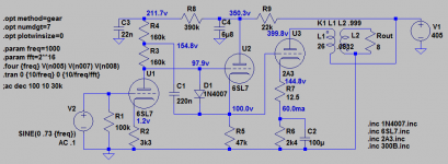
I sized C3 to stabilize the voltage for the input stage. The resistors are quite large and current flow is small, so C3 can be small as well. We can use a nice mkp or pio.Not bad. Is C3 not too small?
I did not yet check the effect PS hum.
I spiced up the cathode follower circuit (3rd schematic post #1) a little. The freewheeling diode protects the 6SL7 during power on. The pre-stages deliver a nice 90 Vpp at 2ma thru the 2nd 6SL7 into the 2A3. Input sensitivity is 0.5V RMS.
THD for the pre-stages at full power is <0.1, with H3 and higher <0.03 for most of the audible range.
THD for the full amp comes predominantly from the 2A3 and consists mainly of H2, which is ~4.7% at full power. H4 is at 0.2, H3 and others is <0.1.
Note, all values from simulation!
Together with the direct coupling, this should make for a sweet amp. I think this sircuit is the one I'm going to use in my next built.🙂🙂
Hi Goldenbeer,
I have lived, eaten, breathed 2A3 DC SE amps now, for the last eight years. Done a LOT of work, a LOT of thinking on this subject, a LOT of listening, and have even wiritten a paper, unpublished , on it.
There are MANY mistakes in this thread, and MANY things that were not considered / overlooked, by you and the others !!!
Contact me through private email, and I will be pleased to privately share with you my DC 2A3 design ideas - on what to do on a DIY build, with references no less. No need to re-invent the wheel. WHAT is the efficiency of your speaker load ???????
My email is drlowmu at GEE Male.commie. I am sure you will enjoy what I share with you !!
Jeff Medwin
Member
Joined 2009
Paid Member
I have been in receipt of Jeff's knowledge too and would heartily recommend anybody who's interested in DC 2A3 amps to contact him.
I've been a very naughty (lazy) boy and didn't build mine yet but I have the parts - I'll be describing my progress here though: http://www.diyaudio.com/forums/tubes-valves/221739-nice-little-valve-amplifier.html
I've been a very naughty (lazy) boy and didn't build mine yet but I have the parts - I'll be describing my progress here though: http://www.diyaudio.com/forums/tubes-valves/221739-nice-little-valve-amplifier.html
Hi Bigun,
Thanks for the kind words. Please email me and we will discuss the latest findings you can apply to the build. I have an idea and a part or two to share, new stuff.
Jeff
Thanks for the kind words. Please email me and we will discuss the latest findings you can apply to the build. I have an idea and a part or two to share, new stuff.
Jeff
Single Ended Amplifier Concept
I made a 2A3 SET amp based on Thomas Mayer concept with 6A6 (wired in parallel, cathode bypassed) at input and ll1660 interstage with great results.
Tried also running 2A3 tubes with 250V p-k @ 45 mA according to Jeff's recommendations and "it's kicking" ! 😀
I made a 2A3 SET amp based on Thomas Mayer concept with 6A6 (wired in parallel, cathode bypassed) at input and ll1660 interstage with great results.
Tried also running 2A3 tubes with 250V p-k @ 45 mA according to Jeff's recommendations and "it's kicking" ! 😀
I made a 2A3 SET amp based on Thomas Mayer concept with 6A6 (wired in parallel, cathode bypassed) at input and ll1660 interstage with great results.
Tried also running 2A3 tubes with 250V p-k @ 45 mA according to Jeff's recommendations and "it's kicking" ! 😀
Cool repoort, cool to know. Glad you are pleased. Did you notice it being less strained sounding ??? The less unbalanced DC on the output trannie helps too, but mainly, at 10 Watts plate dissipation, you get a reduction in thermal stress, its more relaxed and free sounding, and the tubes last 50,000 hours, sounding better, than degrading at 200 hours and SHOT at 2,000 hours !! Called...good design. conservative. Takes a good supply and layout and wiring to execute it well. Cool report. Enjoy !!
BTW, the DC two stage amp we do will EAT any interstage coupled amp, no contest, the way to go !!
Jeff
Last edited:
There are MANY mistakes in this thread, and MANY things that were not considered / overlooked, by you and the others !!!
Many thanks. But why not share your knowledge and experience with the public? I am always interested incorrections or fresh views, and I bet others are as well.
Do a search on the audio asylum for drlowmu or lses. I can summarize it for you in one sentence: Use low dcr chokes in the psu <10R (total less than 20R for the PSU). Use 19AWG Kimber TCSS paralled 3 timesBut why not share your knowledge and experience with the public? I am always interested incorrections or fresh views, and I bet others are as well.
(use three Kimber Kable TCSS which is 19 AWG, teflon coated, and parallels nicely at three, for both the ground and the B+ wiring, throughout the B+ filters, up to the output transformer's feed of the Finals tube.)
If you don't do that you are WRONG and you have a LOW-fi ...amplifier...if you are lucky a mid-fi amplifier. Period.
Not ridiculing his ideas. I haven't built an amp according to his guidelines. So how can I judge his statements. Its just that it seems to me that if you don't agree with his pov you are wrong.
Last edited:
 Jeff your posts are not in the spirit of diyAudio where knowledge is shared openly and not in secretive little dollops, so I am going to ask you nicely once to stop promoting your friend's designs here if you are not free to disclose this publicly to our membership.
I messed a bit with the caps on the cathode follower schematic, and it's pretty final now.
I am currently sourcing some parts to build this puppy, and am in the need for a new input pot. I heard some people prefer 50k to 100k with 6SL7 input tubes. Can someone share their experience?
Thx
I am currently sourcing some parts to build this puppy, and am in the need for a new input pot. I heard some people prefer 50k to 100k with 6SL7 input tubes. Can someone share their experience?
Thx
Attachments
3. Bootstrapped cathode follower
Pros:
- very low distortion of pre-stages at full power
- lowest output impedance, best drive for 2A3
- no need for bypass cap in pre-stage
Cons:
- additional stage, 3 stages total
- introduces additional cap for bootstrapping
- highest distortion at output at full power
- does not seem very popular, untested in RL(?)
All three topologies deliver about 3W rms into 8R impedance speakers using 2.5K primary trannies.
The cathode follower circuit has been sketched up by myself, using details from various sources, but there seems to be no tried and working instance around anywhere, so watch out. There may be kinks or room for further improvement.
Now, my question to you guys.
Anyone who tried these configs can comment on them from RL experience? Is there any mess up or striking error in the 3rd circuit?
Thanks & greetz to all
The bootstrapped follower has been tried: Loftin White: ECC83 300B Darius Loftin White Fortsetzung
But as long as you are at it, why not ditch the output cathode resistor and add the PS noise canceling circuit above. I built an amp based on Darius's circuit and it's my favorite amp. So quiet that it's my headphone amp. I didn't use the bootstrapped follower, but would have no hesitation in doing so. Note also that there is not an electro to be found in the amp or HV circuit.
http://www.diyaudio.com/forums/tubes-valves/125488-loftin-white-801-amp.html
Sheldon
Pardonez moi, but being ignorant about this, why is the "cap bootstrap" required for the cathode follower version?
Also, why 100K for the cathode? seems lowish in current through the driver tube?
Explained here, check the forth figure: Loftin White: ECC83 als Treiber für die 300B, Bestimmung einer Kennzahl
The bootstrap cap raises the impedance across the input plate resistor to 12MOhm, which makes it effectively a constant current source. Normally, a follower is used to lower the output impedance, which argues against a high u tube (with relatively high plate resistance). A high u tube in this instance makes it a better follower in the sense that the cathode more closely follows the grid. Same argument applies for using a large cathode resistor in this position.
Sheldon
Example (easy to change values to suit 6SL7). Fewer parts too:
http://www.diyaudio.com/forums/tubes-valves/128695-2a3-design-issues-long-2.html#post1595084
diyAudio
http://www.diyaudio.com/forums/tubes-valves/128695-2a3-design-issues-long-2.html#post1595084
diyAudio
Last edited:
Perhaps this is another idea to consider.
Jeremy Epstein's Free Lunch
Jeremy took his build to the Euopean Triode Festival a couple of years back, where it was very well received. I have assembled all the parts and should have my build/version done soonish. I'll report back when I am listening to it.
John
Jeremy Epstein's Free Lunch
Jeremy took his build to the Euopean Triode Festival a couple of years back, where it was very well received. I have assembled all the parts and should have my build/version done soonish. I'll report back when I am listening to it.
John
Thanks for all the suggestions, esp. hints from sheldon and listen. The Free Lunch looks great as well, but as I said anode chokes are just not my deal.
First, I wanted to post a correction to the CF schematic, see attached. You can trim the voltages in the system and bias of the 2A3 using the pot.
Then, while pondering lots of schematics, I came back to the tubelabs power drive, and sketched up a variant using no dedicated CCS but using a bootstrapped source follower instead. See 2nd attachment. This circuit obviously introduces a few caps here and there and needs a fixed bias supply, but should be good to deliver some A2 up to 5 watts from the 2A3 easily.
Attachments
- Status
- Not open for further replies.
- Home
- Amplifiers
- Tubes / Valves
- 3 direct coupled 2A3 amps