Slow progress....
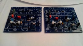
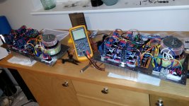
Attached two photo's of the build.
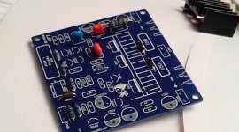
The transistors in the input circuit are matched and thermally coupled.
Also the 10 ohms resistor in the Zobel network hovers above the PCB to improve cooling and prevent burning the PCB in case of disaster.
Yet, a lot has to be done.....
Attached two photo's of the build.
The transistors in the input circuit are matched and thermally coupled.
Also the 10 ohms resistor in the Zobel network hovers above the PCB to improve cooling and prevent burning the PCB in case of disaster.
Yet, a lot has to be done.....
Attachments
Last edited:
matching transistorx
I only used the transistors in the kit.
To my surprise all npn's of the input circuit had about the same hfe.
The pnp's [556] was an other story. Here checking hfe proved to be very useful. Hfe ranged from 277 to 322. Fortunately I maneged to find 5 pnp's around the 320 value. 4 of them would find a way into the diff. Amp.
The 4 pnp's with the largest differences are safe to use in the CC part. 1% deviation in current through the diff amp will have less inpact than 1% difference in the legs of the diff amp, so thats why...
The other transistors? well, there was nothing to match, because one item per amp is rather hard to match if only two are availble.
Request for LJM
LJM,
could you please publish the schematic on which the PCB's are based, for I am unable to find one on the internet that does match the PCB's...
Besides that, the PCB's are a nerve-wrecking puzzle, because of the many bends and curls in the printed tracks... so it's extra hard to track the components and the signal-path..
Helpful for future pcb's would be, not only printing the component values on the mask, but also some other identification like R15, C1, Q3....

Hi
This one probably do not need heatsink , I just bolt them on to chassis surface and they do not get hot after 3 hours of running with music , my one straight of the mill no modification ( oh I do change I/P cap to BP-S bipolar ) , I would say it offer excellence performance for the price I paid , the kit come to last screws , everything you need to complete it 🙂
Regards
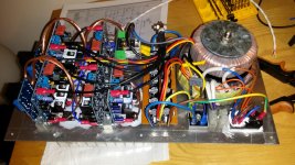
My MX-50se is up and running. It's very nice! I used an old Radio Shack receiver for the chassis, heatsink, & power xmer. Power supply is at 41VDC with 20k farads for plus and minus supply. No heat is generated. It's not pretty. The only problem I had was a bad connection at my RCA input. Completely my fault. For the money, it's impressive...
Here are my SPICE models. Please note I could not find models for all the parts as supplied, so I made fair guesses to some. Not all the parts I used are in the LTSpice library, so you have to hunt them down as I did. Some don;t matter, like using the 1N4001 on the output instead of a 4007. The outputs I modeled are quite good and probably have higher gain.
I am going to use the original parts with the exceptions of the resistors I changed, power supply mods, and additional caps for the compensation. I have everything in my parts box. I hope I have enough stuff to make a DC sense and power up/down circuit. I don't intent to spend any cash on this. Saving that for my Reasonable.
Hi,
The improved version employs TMC instead of the original dominant pole (Miller) compensation. Did you verify THD of the improved circuit and post the result? I would like to see that. Have you built the improved amp? Any listening difference compared to the original one if you have both?
I am trying to improve the original circuit by compensation tuning. Simulation (THD, loop gain) and measurement (THD, loop gain) are used to evaluated "improved amp". http://www.diyaudio.com/forums/solid-state/256034-mx50-amplifier-compensation-tuning.html
Thanks!
Panson
Last edited:
For the money, it's impressive...
That's why I bought three stereo kits.
Finally got enough stuff together to start building.
I still need the output terminals, which still are in transit.
The amp will be set in a partial class A. Also i'll ad a small board to make the setting of the quiescent current easier. In the current configuration thst procedure is quite difficult.
I still need the output terminals, which still are in transit.
The amp will be set in a partial class A. Also i'll ad a small board to make the setting of the quiescent current easier. In the current configuration thst procedure is quite difficult.
Attachments
hi !!
I want you help about - i bought this kit and are missing the transistor 1815
Are these 2sc1815 or something else ?
thank you in advance
I want you help about - i bought this kit and are missing the transistor 1815
Are these 2sc1815 or something else ?
thank you in advance
missing transistor from the kit
hi
I want your help about MX50SE - i bought the kit but the transistor 1815 are missing. D you know these transistirs have type 2SC1815 or something else ?
Thank you in advance
hi
I want your help about MX50SE - i bought the kit but the transistor 1815 are missing. D you know these transistirs have type 2SC1815 or something else ?
Thank you in advance
Hi, The transistors that came with my kit are marked c1815 and are ecb left to right flat side up legs towards you.
I recommend using MX50SE version. Need to pay attention to, don't replace all parts, transistor.
But does not include high power output tube B817 D1047, output power tube according to preferences of free choice,
For example, TTA1943 TTC5200, or SANKEN 2SA1216 2SC2922. A1186 C2837
Pay attention to any other parts, can not replace. They have been optimized measures in the design. DC + - 45V
But does not include high power output tube B817 D1047, output power tube according to preferences of free choice,
For example, TTA1943 TTC5200, or SANKEN 2SA1216 2SC2922. A1186 C2837
Pay attention to any other parts, can not replace. They have been optimized measures in the design. DC + - 45V
Great little amps
I have 10 of these amplifiers for an active speaker project I am building and can thoroughly recommend them - fantastic value for money. So far I have built 4, using the B817/D1047 power transistors that came with the kits, and they work perfectly - 6 more to go. The B817/D1047 power transistors should be fine for the tweeters and small mid-range drive units but I'll upgrade to the NJW21193/4G for the 8" woofers, better value than the Sanken 2SA1216/2SC2922 with very similar characteristics (200W pd with an Ic of 16A). I also have a number of LJM's speaker drive protection kits to protect the speaker drivers - LJM advises no series inductor nor series capacitor which would ruin the response characteristics of my 24dB/octave ESP 4-Way Linkwitz-Riley active crossover.
I have 10 of these amplifiers for an active speaker project I am building and can thoroughly recommend them - fantastic value for money. So far I have built 4, using the B817/D1047 power transistors that came with the kits, and they work perfectly - 6 more to go. The B817/D1047 power transistors should be fine for the tweeters and small mid-range drive units but I'll upgrade to the NJW21193/4G for the 8" woofers, better value than the Sanken 2SA1216/2SC2922 with very similar characteristics (200W pd with an Ic of 16A). I also have a number of LJM's speaker drive protection kits to protect the speaker drivers - LJM advises no series inductor nor series capacitor which would ruin the response characteristics of my 24dB/octave ESP 4-Way Linkwitz-Riley active crossover.
The only change I did in my LJM MX50SE kit is change in gain setting resistor. I used 470R instead of 330R to lower the gain. I hope that it won't compromise stability although higher gain is better for stability. Korean KEC B817/D1047 output transistors are in fact very good transistors (it's equivalent for the Sanyo pair 2SB817/2SD1047) and if you do not intend to push amp really hard they can be used.
Last edited:
Missing LTSpice model files
Hello tvrgeek,
could you please provide the LTSpice model files cordell.txt and ljm_50mx.txt or give me a hint where to get these files.
Thanks
Martin
Hello tvrgeek,
could you please provide the LTSpice model files cordell.txt and ljm_50mx.txt or give me a hint where to get these files.
Thanks
Martin
Here are my SPICE models. Please note I could not find models for all the parts as supplied, so I made fair guesses to some. Not all the parts I used are in the LTSpice library, so you have to hunt them down as I did. Some don;t matter, like using the 1N4001 on the output instead of a 4007. The outputs I modeled are quite good and probably have higher gain.
I am going to use the original parts with the exceptions of the resistors I changed, power supply mods, and additional caps for the compensation. I have everything in my parts box. I hope I have enough stuff to make a DC sense and power up/down circuit. I don't intent to spend any cash on this. Saving that for my Reasonable.
Is there a modified schematic for the MX50SE at more typical power supply ranges - 30-40V DC? I have the 12V one schematic thanks but my amp will be running on circa 32V rails.
Last edited:
Is there a modified schematic for the MX50SE at more typical power supply ranges - 30-40V DC? I have the 12V one schematic thanks but my amp will be running on circa 32V rails.
You don't need to change anything for 32V rails. Use the kit as it is. I intend to use my at 35V rails.
Plate Amps
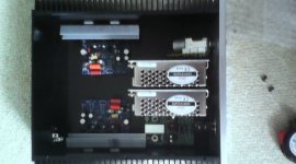
I didn't find that I needed a schematic, although if you need one it's pretty easy to trace one out for the cct bd. It's a standard amp with a nice constant current generator for the long tail pair and a clever active bias current cct. I've included a couple of pictures of the plate amps I've built to go into my speakers (Falcon Acoustics have just got new stock of the SB Acoustics units I'm using, due for delivery on Tuesday). Just to say, of the 10 amps I purchased the kits were all perfect, not a single component, screw or connector missing and all 10 amps worked perfectly.
I didn't find that I needed a schematic, although if you need one it's pretty easy to trace one out for the cct bd. It's a standard amp with a nice constant current generator for the long tail pair and a clever active bias current cct. I've included a couple of pictures of the plate amps I've built to go into my speakers (Falcon Acoustics have just got new stock of the SB Acoustics units I'm using, due for delivery on Tuesday). Just to say, of the 10 amps I purchased the kits were all perfect, not a single component, screw or connector missing and all 10 amps worked perfectly.
Attachments
- Home
- Amplifiers
- Solid State
- LJM MX50 kit amp