Unfortunately it would be difficult to add a protection without losing many of the advantages
It has been done too; I am not sure it has been described in the thread, but I have modded one of mine to serve as a replacement for an amp having a single supply.
That would be the simplest path to a protection
Post #901 !
Thanks Daniel & Gannaji, you spared me some time. The thread is so huge that browsing through it takes forever
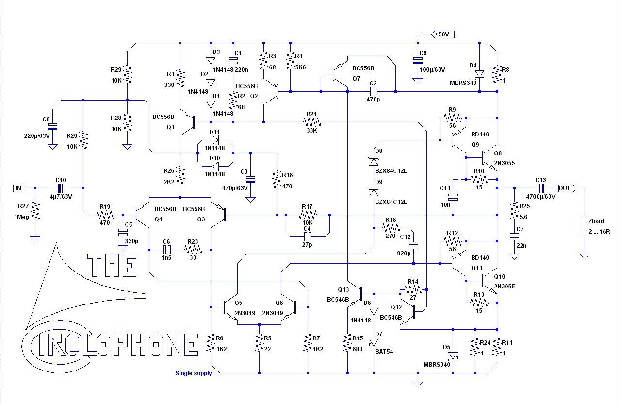
The simplicity of the amp is close to overwhelming! Hopefully i get one ready by year end.
The last but minor problem are pnp alternatives for Q5,Q6. All discontinued.
The last but minor problem are pnp alternatives for Q5,Q6. All discontinued.
BF423, 2N3495, 2N5415....?The last but minor problem are pnp alternatives for Q5,Q6. All discontinued.
BF423, 2N3495, 2N5415....?
I also tried 2sa1370 (200V, Cob=3pF) with good results on my mosfet version. Available on ebay. 2sa1630 is another good PNP candidate It hink.
By far the best documented DIY amp. Great work. Simulation ongoing. Harmonics spectrum will be simulated for different power ( start with 50 mW) at different frequencies, on a reactive load, that is, proven Spice models of 2 way and 2 1/2 way passive speakers. The frequently quoted thd at 20 kHz tells about open loop speed and hence, speed of NFB.
By far the best documented DIY amp. Great work. Simulation ongoing. Harmonics spectrum will be simulated for different power ( start with 50 mW) at different frequencies, on a reactive load, that is, proven Spice models of 2 way and 2 1/2 way passive speakers. The frequently quoted thd at 20 kHz tells about open loop speed and hence, speed of NFB.
Did you decide to use any specific output device? I tried to simulate a "fast" circlophone prior building with 2sc2922's but never find a particular compensation scheme for stable operation with acceptable stability margin. Then I decided to go with vertical mosfets which I found that far easier to find a stable compensation scheme. Easier to build too.
The impedance curves of these 2 speakers are just nasty for some amps. Thus these loads tell more about quality than a resistive load. The problem with fast BJTs becomes obvious when you look at the complete data sheet, there the chart ft vs ie. The easiest way is to compensate for the lowest ft which is about 200 kHz. But doing so, you need not fast BJTs... MOSFets have similar characteristics especially p type but not to such an extend.
Changed back to sim of original Circlophone single rail. Trusted Spice models. But... oscillation with reactive load. With resistive all ok.
Can you post your sim?Changed back to sim of original Circlophone single rail. Trusted Spice models. But... oscillation with reactive load. With resistive all ok.
No oscillation with a tame, amp friendly speaker model. Simple 2 way. Some other amps ( but not those all EF OS topologies ) oscillate with the crazy-impedance speaker models as well. Ok. case settled the circlophone is intended for active speaker anyway.
There have been a few (benign) oscillation issues in some builds of circlophone, but they were related to certain mixes of transistors, not with the load.
In fact, a real-life circlophone is extremely tolerant regarding difficult loads: I have tried to connect directly to the output undamped capacitors and inductors and series and parallel combinations, but never had oscillations, just some ringing on squarewaves for some values.
In this respect, it is generally very well behaved
It is well possible that it is more of a problem of the simulation. The ( hopefully) attached model file may suffer from imprecise models of 2SC2922 when executed
The speaker model here is static, doesn't model speaker EMF.
The speaker model here is static, doesn't model speaker EMF.
Attachments
Last edited:
Class AA and Class A amplifiers don't need high speed outputs because there won't be any switching going on. Also, the capable MJ15003 won't limit the quality.
If you wanted to go with something reliable on both simulator and physical, that is MJL21194, and Bob Cordell has a model for it. Here: CordellAudio.com - SPICE Models
If you wanted to go with something reliable on both simulator and physical, that is MJL21194, and Bob Cordell has a model for it. Here: CordellAudio.com - SPICE Models
Code:
MJL21194_C npn IS=4e-12 BF=70 VAF=500 IKF=14 ISE=1.2e-9 NE=2.0 NF=1.01 RB=3.4 RBM=0.1 IRB=1.0 RC=0.06 CJE=8e-9 MJE=0.35 VJE=0.5 RE=0.01 CJC=1.2e-9 MJC=0.5 VJC=0.6 FC=0.5 TF=21e-9 XTF=90 VTF=10 ITF=100 TR=100e-9 BR=5 VAR=100 NR=1.1 EG=1.1 XCJC=0.96 XTB=0.1 XTI=1.0 NC=4 ISC=0.3e-12 Vceo=250 Icrating=16A mfg=OnSemiDan, you copied that model wrong. Here is the one off of Cordell's site:
Code:
* MJL21194C - created November 22, 2010 copyright Cordell Audio
.MODEL mjl21194C npn
+	IS=4e-12	BF=70 		VAF=500
+	IKF=14		ISE=1.2e-9	NE=2.0		NF=1.01
+	RB=3.4 		RBM=0.1 	IRB=1.0 	RC=0.06
+	CJE=8e-9 	MJE=0.35	VJE=0.5		RE=0.01
+	CJC=1.2e-9	MJC=0.5		VJC=0.6		FC=0.5
+	TF=21e-9 	XTF=90 		VTF=10		ITF=100
+	TR=100e-9	BR=5 		VAR=100 	NR=1.1
+	EG=1.1 		XCJC=0.96	XTB=0.1		XTI=1.0
+	NC=4		ISC=0.3e-12	mfg=CA112210
*Thanks.
All of the variables are the same, except for the last three:
Vceo=250 Icrating=16A mfg=OnSemi
Will that make much of a difference to the model?
All of the variables are the same, except for the last three:
Vceo=250 Icrating=16A mfg=OnSemi
Will that make much of a difference to the model?
- Home
- Amplifiers
- Solid State
- ♫♪ My little cheap Circlophone© ♫♪