A high fT is desired for a "fast" feedback. Those ole tubes are "internally" very fast , the practical amps are severely limited by the transformer at the output. The current feedback topology is insofar better suited for BJT amps as it quite easily allows lead/lag compensation
But anyway, i use just those BJTs in simulation which i actually have. At first. If there are indication of stability issues, continue with other models.
Btw it is a good practice to check the validity of Spice models ... i found models of BJTs which started conducting at Vbe less then 0.4 Volts...
But anyway, i use just those BJTs in simulation which i actually have. At first. If there are indication of stability issues, continue with other models.
Btw it is a good practice to check the validity of Spice models ... i found models of BJTs which started conducting at Vbe less then 0.4 Volts...
Last edited:
Thanks.
All of the variables are the same, except for the last three:
Vceo=250 Icrating=16A mfg=OnSemi
Will that make much of a difference to the model?
Those parameters do nothing except tell LTSpice what to display in the transistor selector. Other than that they are the same (if not, I would need to fix that).
Random SC2922 model found online: 2SC2922 npn Is=122.9n Xti=3 Eg=1.11 Vaf=100 Bf=87.13 Ise=122.9n Ne=1.677 Ikf=99.99 Nk=1.384 Xtb=1.5 Var=100 Br=1 Isc=0 Nc=2 Ikr=0 Rc=0 Cjc=2p Mjc=.3333 Vjc=.75 Fc=.5 Cje=5p Mje=.3333 Vje=.75 Tr=2.581u Tf=4.584n Itf=6.76K Xtf=42.56K Vtf=10But anyway, i use just those BJTs in simulation which i actually have. . . .Btw it is a good practice to check the validity of Spice models. . .
As usual, there is no news about the spice model's validity.
Here's a short list of valid outputs: BD249C, MJ802, MJL21194, MJW21196, MJ21194, MJ15022, MJ15024, MJ15003. . .If there are indication of stability issues. . .
Or,
If you didn't use one of those, here's a bit of post 16:
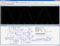
The schematic from post 1, showing C11. . .if you use fast (Ft>5MHz) transistors, the capacitor C11 shown as optional on the schematic becomes mandatory to remove local instabilities. . .
Random SC2922 model found online: 2SC2922 npn Is=122.9n Xti=3 Eg=1.11 Vaf=100 Bf=87.13 Ise=122.9n Ne=1.677 Ikf=99.99 Nk=1.384 Xtb=1.5 Var=100 Br=1 Isc=0 Nc=2 Ikr=0 Rc=0 Cjc=2p Mjc=.3333 Vjc=.75 Fc=.5 Cje=5p Mje=.3333 Vje=.75 Tr=2.581u Tf=4.584n Itf=6.76K Xtf=42.56K Vtf=10
As usual, there is no news about the spice model's validity.
The model was again copied wrong (.model at the beginning left out). Furthermore, no power transistor in this class has 2pF Cjc and 5pF Cje. ABORT!!!
Provided i don't make a big mistake here....forcing a base current of 2 mA yields ie of 145 mA not that bad but Vbe reads 359 mV....that is the 2SC2922 model simple test...
the models provided by Bob Cordell ( and my own model of a general purpose npn ) make good sense.
LT Spice is i think basically a numerical solver of particular classes of differential equations .. it does the job of integration. One cannot expect too much, most models have to be tweaked a lot.
the models provided by Bob Cordell ( and my own model of a general purpose npn ) make good sense.
LT Spice is i think basically a numerical solver of particular classes of differential equations .. it does the job of integration. One cannot expect too much, most models have to be tweaked a lot.
Last edited:
Despite the inaccuracy of the Spice models it appears that the harmonics spectrum is well behaved versus power and frequency. Thus without SOAR and short protection required the circlophone is a really good amp for active speakers. But i am not sure about "rise time".
Besides that most audio signal sources are rather limited in terms of rise time, if a broadband speaker has a rise time of 13 µsec for - 3dB (which is very fast) the amp should at least be twice as fast but other audio scholars claim 10 times as fast. If so the target is ( given 55 volts single rail) about 20 volts/ µsec.
Whether this makes sense or not ( what is the max rise time of a CD ??) the Circlophone is apparently slower , if my sim ist not wrong.
With +/-20V supplies and 2N3055's as OP, the +SR is 24V/µs and -SR 20V/µs (actually measured).
Apart from the unrealistic 2SC2922 model, the oscillation seems to be caused by a known issue: a minor parasitic pole in the common mode loop caused by R15.
It happens with certain mixes of transistors, and the simplest fix is to eliminate R15 completely: it has no active role and just improves ruggedness and strong EMI immunity.
Attachments
Last edited:
Regarding the slew-rate, the base version is shown with a heavy, one-size-fits-all compensation, capable of accomodating very slow OP devices like the 2N6259.
With better devices like yours, you can safely reduce C10 to 180p.
The SR then becomes 50V/µs:
With better devices like yours, you can safely reduce C10 to 180p.
The SR then becomes 50V/µs:
Attachments

Seriously guys, that 2SC2922 model is so bad, it would be more realistic to just use one of Cordell's power BJT models.
Thanx however using Cordell models the sim did not show any instability.With +/-20V supplies and 2N3055's as OP, the +SR is 24V/µs and -SR 20V/µs (actually measured).
Apart from the unrealistic 2SC2922 model, the oscillation seems to be caused by a known issue: a minor parasitic pole in the common mode loop caused by R15.
It happens with certain mixes of transistors, and the simplest fix is to eliminate R15 completely: it has no active role and just improves ruggedness and strong EMI immunity.
The 2SC2922 model fails almost every test especially the ft vs ie tests.
So better drop it.
I think that a class A should exhibit a constant gm , this is due to BJT characteristics only almost possible with Circlophone, and the old single diffused 2N3055 is superb for this , older Germanium power BJTs are even better. But modern types are less suitable.
For replacing those, the MJ15003 is the go-to part (the nearest match currently available). It has also been used on some higher power Circlophones, with satisfying results.I think that a class A should exhibit a constant gm , this is due to BJT characteristics only almost possible with Circlophone, and the old single diffused 2N3055 is superb for this, older Germanium power BJTs are even better. But modern types are less suitable.
sim is ok. with BD250C but some oscillation problems with 2SC5200 model. In terms of psychology of the auditive, distortion is highly problematic for the overall impression. No one would call a double bass or contrabass distorted as the harmonics are much higher in amplitude than the fundamental . So what matters is the falling characteristic of the harmonics spectrum which must be constant vs power and frequency, while the thd has very little impact on subjective impression. In this respect the circlophone is quite good.
There can be multiple models for a single transistor, usually each of them will be flawed in some way. Here is a collection of models that I've tested to be accurate in almost all tests, barring stuff like quasi-saturation which has only recently gained support in the simulator. The important thing is that except in a few situations (very low Vce unless it models quasi-saturation) they shouldn't give misleading results.
Code:
* Version 7:
*
* Changed Rb value for BC3x7_kq, for accurate noise analysis
*
* Models collected by keantoken of the DIYAudio.com forums.
* All of these models should have quorum and not have any misleading or overly false attributes.
* If so, please let me know on the forums.
* This list may be revised/updated at any time, so keep an eye out.
* Version number before the decimal denotes an improvement in the quality of the models.
* After the decimal indicates cosmetic or organization changes.
*
* EXCEPTIONS:
* 1: Precious few models have quasi-saturation; the parameters have only recently been available to provide this.
* 2: No models currently have breakdown voltage modeling - however parameters exist for this: BVcbo, nBVcbo, etc.
*
* IMPORTANT: You may replace your standard.bjt file in /lib/cmp/ with this one, but you must make it read-only or LTSpice will just write over it with the dubious default model set - WITHOUT TELLING YOU.
*
* Suffix indicates the origin of the model:
*
* _C - Bob Cordell of DIYAudio
* _A - Andy_C of DIYAudio
* _D - Harry Dymond of DIYAudio
* _k - keantoken - me
* _kq - My models which have quasi-saturation!
* _S - Syn08 of DIYAudio
*
* Models without a suffix were found unattributed or were provided by the vendor specified in the model. Manufacturer, Vce and Ic parameters were added to integrate the models better with the LTSpice interface.
Attachments
Thanx i have a collection of models some are severely flawed some a bit flawed. Very nice to hear you have done tests already.
Soon i should have a real circlo ready and then comes the next part..make it a good driver of active woofer...and another a driver of fast broadband....
Soon i should have a real circlo ready and then comes the next part..make it a good driver of active woofer...and another a driver of fast broadband....
In order to save newcomers from reading the 128 pages of this thread, someone should answer a few basic questions about this design:
Is the circlophone a repurpose of the krill output stage?
Is global negative feedback used?
Has does the harmonic distortion profile differ from the krill?
Is the circlophone a repurpose of the krill output stage?
Is global negative feedback used?
Has does the harmonic distortion profile differ from the krill?
In order to save newcomers from reading the 128 pages of this thread, someone should answer a few basic questions about this design:
Is the circlophone a repurpose of the krill output stage?
Is global negative feedback used?
Has does the harmonic distortion profile differ from the krill?
You may refer to post#325
Thanks. As I understand this, we have a basic Hood amp with the input and phase splitter combined in a driver array that the servo keeps in constant operation to force the outputs into constant swing. "Vely cleva Mr. Bond", so where is the feedback in the output pair and what is the harmonic profile?
The Circlophone is an active-switching class AB amplifier, which is very different from the Krill and results in a different harmonic profile.
Yes, GNFB is used. The Circlophone is a pretty normal frontend augmented to provide active switching for the output transistors.
I think the Krill has less high-order harmonics. The Circlophone still has a blip during crossover.
Yes, GNFB is used. The Circlophone is a pretty normal frontend augmented to provide active switching for the output transistors.
I think the Krill has less high-order harmonics. The Circlophone still has a blip during crossover.
I made a somewhat messy breadbord implementation. I don't have any equipment to measure the harmonics spectrum thus i tested for stability of the quiescent current vs. temperature. I used my very old function generator - ICL 8038 based- which has a burst facility. Using 8 waves burst 8 pause at assumed - 3dB out power where dissipation should be maximum, with an old scope ( Hameg) i measured the emitter currents of the output BJTs via voltage across emitter resistors. The currents are almost incredibly stable. I calculate the junction temp to reach up to 100 degrees.
In more advanced HiFi magazines the phrase " fine dynamics" is recently stressed, and related to stability of current. In that respect, the circlophone should do very well.
In more advanced HiFi magazines the phrase " fine dynamics" is recently stressed, and related to stability of current. In that respect, the circlophone should do very well.
- Home
- Amplifiers
- Solid State
- ♫♪ My little cheap Circlophone© ♫♪