Will the NX-amp be able to run cool on this radiator?
H : 84mm L: 246mm, base plate thickness 5mm
One radiator for each of the channels.
H : 84mm L: 246mm, base plate thickness 5mm
One radiator for each of the channels.
Solviken, that radiator is a bit thin.
Your heatsink length and width size is about right. Typically the solid part will be about 10 mm and then with the fins on top of that another 30 mm for a total depth of 40mm.
You of course can try it, but I think it will run hotter than it should for a class AB and the thermal stability will not be as good as it should be.
Can you post a picture
Anyway, good luck with your project!
Last edited:
I havent started my project yet. I have onbly bought the boards from Jims Audio. Still searching for what case i wanna use. i have set my eyes on this one
New Black 2109 Full Aluminum PSU Box Power Amplifier Enclosure Cover Slotted SN | eBay
New Black 2109 Full Aluminum PSU Box Power Amplifier Enclosure Cover Slotted SN | eBay
That might be a bit small. Remember, you need to add the power transformer of at least 400 VA if you want the full power. Try to get something a bit bigger.
Do you have the dimensions?
Do you have the dimensions?
what is the board dimensions of the version 2 kit? (the psu as aswell)?
What about going for a size bigger case, with a heatsink this size H:110mm L:246mm Thickness of the substrate:5mm?
What about going for a size bigger case, with a heatsink this size H:110mm L:246mm Thickness of the substrate:5mm?
Last edited:
This is the one I'm looking at
Professional Aluminum Chassis Case Enclosure FOR Amplifier 430 150 314mm | eBay
The case is whats holding me up.. Rather expensive for the shipping..
Professional Aluminum Chassis Case Enclosure FOR Amplifier 430 150 314mm | eBay
The case is whats holding me up.. Rather expensive for the shipping..
Try Siliconray - they advertise on the vendors thread
Another good one is Modushop
That housing looks about right size wise Joel
Another good one is Modushop
That housing looks about right size wise Joel
what is the board dimensions of the version 2 kit? (the psu as aswell)?
+ additional question: what is the minimum height of heatsink to adopt NX pcb board successfully?
Hi Bonsai ,thanks for reply.Nice looking chassis Thimios - looks like it will handle the sx-Amp well!
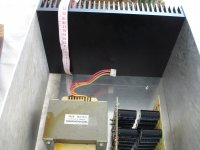
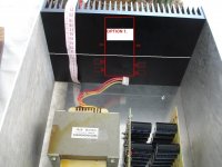
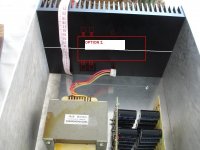
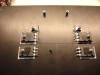
Can you advice me for proper installation way?
You prefer option 1 or 2.
Keep in mind that each heatsink consists of two smaller.(white line shows this.)
Attachments
Last edited:
Board dimensions are same as version 1 no change
Amp board 4.4 inches x 4 inches
PSU +Prot board 4.5 inches x 3.2 inches
nx and sx amplifier boards are same dimensions (THP ones).
Amp board 4.4 inches x 4 inches
PSU +Prot board 4.5 inches x 3.2 inches
nx and sx amplifier boards are same dimensions (THP ones).
Hi Bonsai i have two questions again🙂
1)I wonder if it is big disadvantage if we leave C1=10uf unpopulated (i haven't this thing).
2)Why the differential transistors aren't thermal coupled?
1)I wonder if it is big disadvantage if we leave C1=10uf unpopulated (i haven't this thing).
2)Why the differential transistors aren't thermal coupled?
You can leave C1 off - it just filters any remaining HF noise from the offset adjust circuit out.
For the input transistors, the diamond buffer arrangement cancels 1st order Vbe and delta Vbe with temperature. So, in its basic state, it's already quite stable and provided there are not big temperature deltas across the transistors (which there are not in practice) they track over temperature very well. They are in close enough proximity to do the job very well in both the sx and nx amplifiers.
Follow the set up instructions in the build document.
In practice, when you switch on, the offset will be at max, and then after a minute or two will quickly settle down to within a few mV (4-5 mV) of its final value. After 5 -10 mins, it will be within 1-2 mV of 0.
Why is the cold offset bigger than the warm offset and then much big than the fully warmed offset?
Which components are responsible? Which parameters are responsible?
I ask for two reasons:
1. to know what to try to avoid in future.
2. I have in old DC servo Threads suggested that the amplifier, needing the servo to attenuate output offset, be set up to have zero (or very near zero) offset at switch on and for the servo to control the DC conditions so that as warm up progresses the servo applies correction to maintain that low, or near zero, offset.
Last edited:
The sx and nx-amps are DC coupled - there is no servo. Instead, the DC offset is trimmed for 0 mV output when the amplifers are warmed up.
After initial calibration and set up, the offset at cold after any subsequent power up is around 40mV (measured on 8 protos and final amps for sx and nx amp). This is already quite low for a DC coupled, non servo'd design.
If you follow the offset calibration procedure, you will note that the offset is dialled out after the amplifer has warmed up and the heatsonks have reached their operating temperature (on the class AB nx-amp its around 10~15 degres above ambient at normal listening levels, and maybe 20 degrees on my iterations at higher power levels).
So, this is the reason the offset is at max on subsequent power-up cycles.
The gain of the nx-amp is about 34 x. So, with a ~40mV offet at switch on, this implies a total input stage offset is a little over 1mV (The sx-Amp gain is ~14x)
The repeatable output offset after the amps have warmed up are around 1~2 mV and > 80% of the initial offset settles out within 2~3 minutes of power up.
Last edited:
I asked what components give the cold output offset and what parameters of those components give the cold output offset.
I am NOT suggesting you redesign your NX/SX amplifiers. Nor am I suggesting you need consider adding a DC servo.
I am NOT suggesting you redesign your NX/SX amplifiers. Nor am I suggesting you need consider adding a DC servo.
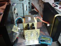
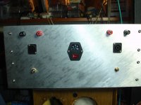
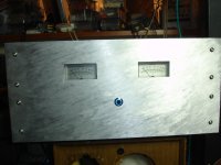
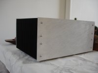
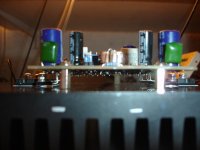
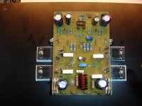
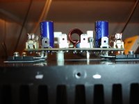
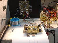
Sx
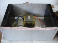
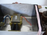
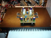
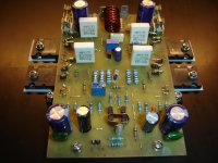
First channel housed and running .
Second on the road...
First channel housed and running .
Second on the road...
Attachments
-
 DSC08388.JPG576.3 KB · Views: 198
 -
 DSC08386.JPG568.7 KB · Views: 196
 -
 DSC08385.JPG495.9 KB · Views: 199
 -
 DSC08384.JPG565.8 KB · Views: 222
 -
 DSC08382.JPG600.2 KB · Views: 227
 -
 DSC08381.JPG520.6 KB · Views: 418
 -
 DSC08380.JPG568.4 KB · Views: 427
 -
 DSC08379.JPG556 KB · Views: 436
 -
 DSC08389.JPG588 KB · Views: 210
Last edited:
- Home
- Amplifiers
- Solid State
- SX-Amp and NX-Amp