Joel,
Hmmm that's a little lower than I would have expected. Usually aim for o.5 to 1 uH. Suggest you use slightly thinner wire and wind for 0.6 uH
Can you post a picture when you are done? I used a 1% cap, a 1 % resistor and a sig gen to check mine. Clearly it's off by about 15 %.
Thanks for picking this up BTW
The NX document specifies 8 turns of 2mm wire (#12 AWG) on a 10mm former. I calculated the inductance of a single layer coil with these dimensions and got 0.41uH. If the coil is changed to 10 turns of 1.6mm wire (#14 AWG) on a 10mm former the calculated inductance rises to 0.6uH.
Thanks Bill - I'll add a note on that to the write-up when I update it next.
My signal generator has a digital read out - I suspect that plus the cap and resistor tolerances are what led to the error since I wound and measured.
What formula did you use to calc the inductor? I heard that for air-cored inductors if the dimensions did not fall within certain parameters the standard formulas gave errors.
Code:
NX Amplifier Output Inductor

8 turns of 2mm diameter wire on a 10mm coil form
2mm = 0.079" -> #12 AWG -> 0.081" = 2.06mm diameter
#12 wire enameled tightly wound is 12 turns per inch
8 turns / 12 turns per inch = 0.667 inch
N = 8, l = 0.667", r = (10 + 2.06) / 2 = 6.03mm = 0.237"

      2  2                2   2
     r  N            0.237 * 8
L = -------- = ---------------------- = 0.41 uH
    9r + 10l   9 * 0.237 + 10 * 0.667

********************************************************

10 turns of 1.6mm diameter wire on a 10mm coil form
1.6mm = 0.063" -> #14 AWG -> 0.064" = 1.63mm diameter
#14 wire enameled tightly wound is 15 turns per inch
10 turns / 15 turns per inch = 0.667 inch
N = 10, l = 0.667", r = (10 + 1.63) / 2 = 5.82mm = 0.229"

      2  2                2    2
     r  N            0.229 * 10
L = -------- = ---------------------- = 0.60 uH
    9r + 10l   9 * 0.229 + 10 * 0.667
The formula should be accurate as long as the length of the coil is not wildly different than its diameter.
Thanks Bonsai!
Got it now.. 10 turns of 15 gauge around 10mm former.. This equals 0.6uH..
I'm using a DER EE, DE-5000 with the 2" test leads..
I'll post some pictures later..
Thanks Again,
Joel
Got it now.. 10 turns of 15 gauge around 10mm former.. This equals 0.6uH..
I'm using a DER EE, DE-5000 with the 2" test leads..
I'll post some pictures later..
Thanks Again,
Joel
That's quite a big error.
Fortunately there is a wide margin.
Could you add 1 more Turn and measure again?
Diameter is critical since L varies with D²
Length is not as bad.
BTW, 8 turns probably ends up as 7¾ turns. That too makes a significant difference.
Fortunately there is a wide margin.
Could you add 1 more Turn and measure again?
Diameter is critical since L varies with D²
Length is not as bad.
8Turns needs a diameter of ~15mm for 0.6u to 0.7uHThe NX document specifies 8 turns of 2mm wire (#12 AWG) on a 10mm former.....................inductance rises to 0.6uH.
BTW, 8 turns probably ends up as 7¾ turns. That too makes a significant difference.
Last edited:
How critical is the actual inductance? Isn't this trying to take care of feedback from the speakers and cables? Those can vary greatly from one user to the next.

Thanks Joel, Bill_P and AndrewT.
Having the inductor at 0.4 uH will not lead to problems - the ULGF phase margin is >60 deg and the amp can handle a wide range of capacitive loads (from sims and real world tests).
But, I prefer to get these things right, so I suggest we go with 10 turns of 1.6mm wire at 10mm diameter for all new builds.
For amplifiers already built with the 8 turns , you should leave them be - they will be fine.
I have already updated the documentation - when I next do an update on my website, the new winding details will appear in there. In the meantime, I will just update the first post in this thread.
😎
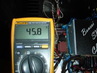
First ,room temprature
Second ,heatsink temperature.
Hello Thimios - what is the time difference between the two measurements?
If thats your final temp - its good. My amp runs at about 55 C (over 60 when the weather is hot) so you should be good to go.
The first picture isn't the amplifier temperature but the living room(house) temperatureHello Thimios - what is the time difference between the two measurements?
If thats your final temp - its good. My amp runs at about 55 C (over 60 when the weather is hot) so you should be good to go.
On the second picture is the heatsink temperature after 5 hours continuous function.
...............
Fortunately there is a wide margin...............
I said in response to the question.How critical is the actual inductance? ..............
Q3 is not labelled on my amp boards.. No biggie
These SMD transistors, feels like I'm handling little Crabs😛
Getting better job with the SMD's as I go along, but I should get a finer tip for future work..
Any Comments on the main use of SMD devices in SS amps? lower noise, faster recovery, shorter signal paths or???
These SMD transistors, feels like I'm handling little Crabs😛
Getting better job with the SMD's as I go along, but I should get a finer tip for future work..
Any Comments on the main use of SMD devices in SS amps? lower noise, faster recovery, shorter signal paths or???
Pinnocchio
Seem like you finish your nx amp. Could you compare it to the first one. I would like to build CFA but don't know which one to build.
I own both but have not really compared them yet since the NX Amp was on a temp heatsink before and was getting too hot to listen for me than 15 minutes, actually I had both modules on a HeatsinkUSA 10.080" profile 6" high, it was far than ideal! Now with my build almost done it will be a different game! 😀
I do remember it to be extremely dynamic and musical and the image depth was one of the best I've heard to date. More later when I'm finished with the build.
One thing I love about this amplifier compared to the FO is that it is a fully DIY project compared to the FO which is already assembled, so you get more hands-on.
Ciao!
Do
FO comparison with NX (lateral to BJT) will never be apple to apple imo. I have simulated NX but I forgot how it look. But I think diamond buffer tends to exaggerate low order distortion, which many people tend to like BTW. And of course, the transconductance is one of the most important aspect that make people enjoy the music.
You can actually see my progress trail in here (French only).
Ampli NX Amp (version originale Hifisonix (Bonsai)) - Page 2
It is one hell of a good amplifier this NX!!!
Ciao!
Do
Ampli NX Amp (version originale Hifisonix (Bonsai)) - Page 2
It is one hell of a good amplifier this NX!!!
Ciao!
Do
Since Bonsai put so much effort to bring us this amazing NX Amp, it is only fair that I start posting some pictures of the final build which I'm doing now.
Here's the Amp module and PSU side by side. I wanted to minimize cable length and optimize it so not too much cabling would show up.

Here's the capacitors I'll be using, the other ones in the above picture was just to test the PSU. I'm configured in a dual mono setup so I will have two PSUs and two transfos or a single transfo with quad secondaries.
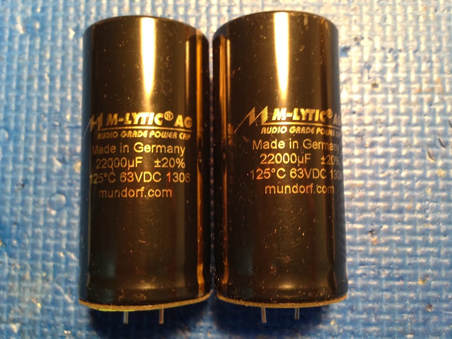
BTW, this amplifier sounds really good!
Ciao!
Do
Hi Pinnocchio,
Impressive build you have here! 🙂
Does the amp pcb you used fits in a 3U (12 cm) heatsink/chassis? How large is the pcb?
Happy New Year! 🙂
Last edited:
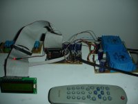
Today is another listening day.
A PGA2311A based preamplifier (posted in Elektor) drive the SX amplifier.
Away sound!
Death silent even with ear in woofer!
Wonderful sound ,i listen again and again the (Pink Floyd) "High Hopes.
A PGA2311A based preamplifier (posted in Elektor) drive the SX amplifier.
Away sound!
Death silent even with ear in woofer!
Wonderful sound ,i listen again and again the (Pink Floyd) "High Hopes.
Attachments

Today is another listening day.
A PGA2311A based preamplifier (posted in Elektor) drive the SX amplifier.
Away sound!
Death silent even with ear in woofer!
Wonderful sound ,i listen again and again the (Pink Floyd) "High Hopes.
That's great! I agree, both the nx and sx are great sounding amps. I left my sx on the heatsinks, intending to complete it some day.
Blessings, Terry
- Home
- Amplifiers
- Solid State
- SX-Amp and NX-Amp