Hi Chris,
It's just the nature of the input resistor and feedback scheme on the differential amplifier.
If you look at the schematic, you'll notice the input connects directly to the output via the input resistors (1K) and the feedback resistors (1K) which means that when the power is off, your DAC is directly driving your headphones through a 2K resistor on each phase.
Owen
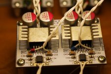
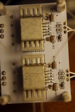
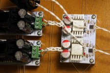
Darn! This is most likely why I get decent sound through the balanced outs and no sound when trying the positive out and ground. Here are some close up photos for help, but are there also voltages I could look for at specific points on the circuit to help? I don't remember seeing a post with any. I did test each solder for continuity as I went ( my first smd project)--but also ended up using an awful lot of heat on the top 49600s, since I had tried the "slight lump of solder under neath and then heat it until you get it to drop down" technique that had been posted. My first place to check would be if I fried these. Both power supplies seem to be working fine.
Any help would be appreciated!
Attachments
Last edited:
Are you're input wires correct? If balanced you have no earth input? If single ended you should connect to the centre and one side?
Are you're input wires correct? If balanced you have no earth input? If single ended you should connect to the centre and one side?
My DAC (source I'm using) only has pos and neg outputs- so I didn't bother with them here. DAC works fine into rest of my system, which is all differential/balanced. I'm certainly willing to try this though!
Last night I built the SE while still trying to figure out why the Bal Bal isn’t working. SE is DELIGHTFUL! Powers my HE-560 with great ease. I built it with 3x gain, which I need on quiet recordings. Will be a gift for my son, but will also build one for myself.
Back to my problems with the Bal Bal—
1. If my assumption that I burnt one or more of the 49600s is correct, how can I tell? I will be ordering more. Is there any kind of test while in circuit? I looked at the TI data sheet, but don’t see a way from that to tell. (On the other hand, I couldn’t pretend to understand much of what is there.)
I have gone all around the board again and tested all point to point solder joints for connectivity, and all test fine.
2. One idea I had is that the wires I used for input and output are only very lightly tacked on, since I know I will be replacing them for a final installation. Do any of these need to be more solidly soldered, in case I am not making an internal copper layer connection that a “flow through” solder joint would make? The power connections are very solid.
Any help would be appreciated!
1. If my assumption that I burnt one or more of the 49600s is correct, how can I tell? I will be ordering more. Is there any kind of test while in circuit?
You should get an OK from opc first before trying this suggestion in case I've missed something, but here is a procedure that I came up with to test LME49600's in circuit (this is from a different amp, but same chip), steps 2 & 3.
Essentially what you are doing is breaking the feedback loop by carefully cutting pin 2 (the input pin) on one of the buffer chips with your flush cutters (near the SMD pad end of the lead) and then grounding the pin 2 lead with a test clip. Then measure the output voltage of the buffer chip with respect to ground. It should be somewhere around the datasheet offset level of 0mv to +/-60mV. If you get some voltage way outside that range then the buffer is probably bad. If you have access to a signal generator you could also inject 1.4Vac(peak) or so into pin 2 WRT ground and you should get the same voltage out on a (AC) DMM (=1Vrms) or scope, plus or minus that DC offset level shift. Headphones unplugged for all of this, of course, but a 470R 1/2W or so load resistor on the amp output wouldn't hurt to draw some load current through the buffer.
Once you are done with the test just take the end of a small gauge wire, tin it, then use it with your iron to repair that pin 2 connection to the SMD pad.
But... from my experience so far with the LME49600 it is pretty darn tough with respect to soldering heat. I would wager a problem with the chip(s)/parts driving it first. If there is any buffer damage it is much more likely to be from static while handling.
Last edited:
Thanks agdr; I’ll see if opc chips in and if not will try this.
I have gotten very casual about static the past few years. My iron (Hakko) is grounded, and we generally don’t get much of any static shocks (I sure don’t miss those!) in northern California; I think there’s generally enough humidity to keep it at bay. But I do have a wrist strap and pad, and should use them. Thanks for the reminder.
I have gotten very casual about static the past few years. My iron (Hakko) is grounded, and we generally don’t get much of any static shocks (I sure don’t miss those!) in northern California; I think there’s generally enough humidity to keep it at bay. But I do have a wrist strap and pad, and should use them. Thanks for the reminder.
picovolt - sounds like you have all the right anti-static stuff!
Steps 5 & 6 in that procedure may also be useful. If the buffer(s) test OK, before patching up pin 2 you might want to take a DC reading on the output of the previous stage driving pin 2, which would just be the pin 2 SMD pad, with the amp input grounded (if SE). I'm not sure what the equivalent to grounding the amp input would be if balanced, maybe shorting the balanced inputs together?
Another tip on the LME49600 pin 2. OK to bend it up a little so that it sticks straight out, but much more than that and it may break off (lol - I speak from experience). With it bent out straight you can probably get some small gauge solder wick in there to clear the lead remnants of the pin 2 SMD pad. Then when pin 2 is bent back down it will nearly touch the pad anyway. You may be able to just solder it directly without using any additional wire as a bridge.
Last edited:
With open/shorted inputs, shorting the output shouldn't increase current draw to the point of saturating the transformer as far as I know. Sounds like you're gonna have to grab the DMM and hunt for shorts (or just suspiciously low resistances; you have a working reference channel to compare your measurements to so that's quite handy) - you mentioned the caps (which ones?) getting hot, does anything else get hot? It's possible to fry MLCCs, I recently managed to do that on a pupDAC by being obsessive about getting perfect "machine-quality" joints and reheating/wicking one MLCC one time too many. Usually it's the active/semiconductor components (or bridges between their pins) causing shorts like that but passives can and do fail as well from time to time.
Another thing to watch out for is stray copper strands from multi-strand wire that may end up on the board when stripping wiring isolation. Those can be very hard to see and have a nasty tendency to end up somewhere well-hidden shorting supply and ground pins.
Also, what's that greyish thing between the two lower right pins on the upper op-amp? Looks a bit suspicious to me, but may just as well be an image artifact or something. Try taking some high-quality, well-lit pictures of both sides of the board and someone might be able to see what's going on.
I'd recommend reflowing all joints on the board and cleaning it real well (i.e. bathe it in isopropanol and give 'er hell with a toothbrush) afterwards anyway - some joints look rather scrawny. I can't see any obvious shorts on that pic though, but I also haven't seen the other side yet.
Hi,
Problem solved, bad solder on one of the Vin cap. I'll need to replace it as almost blow when testing several points with the MM.
I unsoldered one cap from the other side of the amp, resoldered it carefully on the non-working side and the buzz from the trafo went off. I'll need a new cap now to follow up with in-depth testing.
Cheers for help, next time I'll take pictures to check all solder points 😉
neofeed:
Glad you got it all up and running! Good work hunting down the issue.
Picovolt:
It's most likely you have a bad solder joint somewhere, but it's also possible something else is wrong. It can be exceedingly hard to spot bad joints visually, as sometimes the solder pools nicely over the pad, but never actually bonds to it. I've seen this a few times. Not sure if it's from aged flux, some residue on the pads themselves, or just not enough heat.
The problem with those bad joints is that when you probe them to measure if the resistor is good, everything looks fine because the solder is connected to the part, but not the pad. That's why, when you measure a part, you need to find adjacent pads on the same net and measure from there instead of the actual pad the part is soldered to.
If you're 100% certain every joint is good, then start by looking at the OPA1632. If you aren't running any direct GND reference between your source and the headphone amp, as shown in the pictures, it's easy to exceed the maximum input common mode voltage of the op-amps and destroy them. Even small transients from the mains, or any static discharge can cause a large potential difference between the GND of each chassis, which in turn will damage the op-amps.
If you replace the OPA1632 and still see the problem, then the last option is to replace the buffer, which is the least likely culprit, even given the heat they may have been subjected too. As agdr mentioned, they are pretty robust.
Testing as per agdr's recommendation first is an excellent idea, and saves you pulling out a perfectly fine buffer.
Give it another once-over and let us know what you find!
Regards,
Owen
Thank you agdr and owc for your help and suggestions. My balanced cable came in yesterday, and I decided to give it a shot last night, since the amp seemed to work with the one loose speaker I had, just not when I tried using it SE. Short story—it works, and I’ve decided to hold off on sorting out what the issue with using it as SE is, and just enjoy the music.
Especially with a brand new cable, I’m holding off on any sonic descriptions until everything has a chance to settle in some, but it already sounds quite nice.
I have been moving parts around a bit, trying to induce some AC hum, so I can figure out how compact an enclosure i can fit this into. So far, I have been unsuccessful in getting the S/N any lower—it just stays dead quiet (this is with less efficient headphones though, but as a balanced amp, that’s what I’m using them with, at least for now).
So now I’m starting to look into Lowther and Fostex drivers, thinking about setting a system up using the 16 watt designs... (Not my first time thinking about these drivers; one of the most expressive systems I’ve ever heard was Lowther / First Watt based.)
Owen—thank you so much for making these designs available, for the continued aid and support you give on the forums, and for making the boards available.
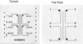
Transformer polarity
That may not even be the correct term. I've been working with toroids for a long time, and have gotten a flat pack to use in the SE build that I'm doing. Looking at the diagram, for 117 V I parallel Blue/Violet and Grey/Brown with a toroid. With a flat pack, should I pair 1/3 and 2/4, or 1/4 and 2/3?
Then, for the two secondaries, 5/6 and 7/8 are definitely the pairings, BUT, is there a best order to wire these into the pos and neg rails of the PS?
Attachments
Check the "pairings" with a resistance meter, or continuity meter.
Check for multiple taps off one winding.
Assume the black dot indicating phasing is correct.
Use a Mains Bulb Tester to power up the primary alone, nothing on the secondaries, which are adequately insulated to prevent accidents.
You can connect just one 110/120Vac primary to the 110/120Vac mains at a time.
You don't need to connect both at this first stage. It will work safely.
If the bulb filament is completely OFF, then your primary is not drawing excessive current.
Now to both primaries: Taking that first phasing assumption as correct, connect both black dot primary leads to Live and both unmarked primary leads to Neutral. Power up via the Bulb and see if the bulb still appears OFF. OK.
If the bulb lights then one of the phasing dots is incorrectly marked. Swap one (only one) pair of primary leads. Power via bulb. Is it OFF this time?
That's the safe way to test the primary wiring of a dual primary transformer.
A primary wiring fault via a bulb tester does not damage the transformer, does not damage the fuse and most importantly does not damage you.
This also works for series connected primaries for 220/240Vac mains supply.
Last edited:
The left iagram in post2271 showing one pair of primary windings as Blue/Grey and the other pair as Violet/Brown is designed for compatibility to The European colour codes for Mains wiring.
Connect the Violet to the Grey. The two remaining taps are Brown and Blue.
In Europe, Brown is Live, Blue is Neutral.
Connect the Violet to the Grey. The two remaining taps are Brown and Blue.
In Europe, Brown is Live, Blue is Neutral.
^^ that would be for 220/230volt though.
But thanks for the answer--I'll absolutely use a bulb to make sure the polarities are correctly marked. Is there a best way to hook up the secondaries to a binary supply? What I typically do is wire them so that the hot always hits the diode bridge in the same location, but I wonder if I should put the neutral there instead for the negative supply, if this would keep both supplies more in phase. (Or make them out of phase-- I've tried diagramming this and am baffled, which doesn't take much to begin with...)
But thanks for the answer--I'll absolutely use a bulb to make sure the polarities are correctly marked. Is there a best way to hook up the secondaries to a binary supply? What I typically do is wire them so that the hot always hits the diode bridge in the same location, but I wonder if I should put the neutral there instead for the negative supply, if this would keep both supplies more in phase. (Or make them out of phase-- I've tried diagramming this and am baffled, which doesn't take much to begin with...)
Do you have three secondary wires? = CT secondary.
or
have four secondary wires? = dual secondary.
or
have four secondary wires? = dual secondary.
^^ 4 secondaries—Owen’s power supply wouldn’t work with a center tapped (or it might but would need more careful isolation of the regulators?).
One pair of secondary tappings go to one rectifier. The output of the rectifier goes to the smoothing capacitor.
Repeat for the other secondary.
All the wire pairs should be twisted into the rectifier and out of the rectifier.
The alternative is to convert the dual secondary to CT by combining the two middle wires.
Then take the twisted triplet to the rectifier. Pass the CT across the rectifier and join it with the two output wires from the rectifier.
Take this next twisted triplet to the two series connected smoothing capacitors.
Hi Andrew,
All understood. What I’m asking is if there is any difference in how each secondary’s twisted pair is connected to the bridge. I know that it’s all AC at this point, and that after regulation and smoothing etc., its pretty clean DC—so I don’t imagine it really makes a difference. But, since we’re dealing with a bipolar supply, would having the two legs not starting off in phase still have any affect? Again, I don’t think so, but I do get surprised at my lack of knowledge.
All understood. What I’m asking is if there is any difference in how each secondary’s twisted pair is connected to the bridge. I know that it’s all AC at this point, and that after regulation and smoothing etc., its pretty clean DC—so I don’t imagine it really makes a difference. But, since we’re dealing with a bipolar supply, would having the two legs not starting off in phase still have any affect? Again, I don’t think so, but I do get surprised at my lack of knowledge.
The "pairs" must be the Flow and Return of ONE circuit.
A dual secondary has TWO circuits, therefore it must have TWO pairs.
A dual secondary has TWO circuits, therefore it must have TWO pairs.
Dear All,
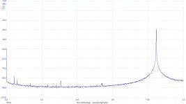
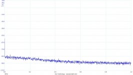
I have one of the very first version of the balanced-SE "The Wire" headphone amp, that I have been mainly been using as a bal-se converter. Now I was always hearing some noise when I was using the headphones that I never manage to see with the scope. Today I understood: the circuit oscillates only when the headphones are connected. Any hint on how to fix this ? The headphones are Audio Technica AR900. Attached the FFT.
The circuit in nicely enclosed. I guess I could reduce the bandwidth a bit.
Thanks,
Davide
Attachments
- Home
- Amplifiers
- Headphone Systems
- "The Wire" Ultra-High Performance Headphone Amplifier - PCB's