BAL amp and gain, with pot:
Forgive me for asking what I should understand by now:
I think gain is Rf/Ri, and from the thread note that if I want to use a pot, 10 K should be a good value (works fine with my source), I should up Ri and Rf to 10K. So—with a 10K pot and 10K Ri, is the input impedance 5K? does this mean that for a gain of 2, I leave Rf at 10K?
I'm also wondering if anyone has experience with Welwyn 5ppm .1% resistors? The 5ppm is attractive to me, assuming that there's usually a correlation between noise and the the ppm ratings.
trying to put a volume control inside a balanced impedance connection is not easy.
This difficulty is made easier by converting the balanced impedance signal to single ended, i.e. unbalanced, controlling the volume and then converting back to a balanced impedance signal.
This balanced impedance complexity is generally only required where extreme attenuation of interference is required to obtain adequate performance from the system.
For domestic use where long runs and high levels of interference don't exist, the need to bal> unbal> vol pot> bal> receiver is just too many stages that are not normally required.
The Wire and V-Moda XS
Hi,
I am a happy builder and user of The Wire with Sennheiser HD600.
The amp also correctly worked with a number of cheap headphones I used for testing it before connecting the HD600.
I have also portable V-Moda XS. I connected them to the Wire via a plug adapter from 1/8" to 1/4" but the sound level is very low and clearly low-fi like a distant sound from an old radio. On the contrary the V-Moda correctly work with the C-moy amp I also built.
I changed the adapter without success.
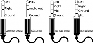
Please note that the V-Moda have a cable with microphone for smartphone use which adopts the Apple 1/8" jack.
I replaced the cable with standard 1/8" to 1/8" jack I already have but the V-Moda does not work at all, even with the C-moy.
have you any idea of the problem?
Thank you
northernsky
Hi,
I am a happy builder and user of The Wire with Sennheiser HD600.
The amp also correctly worked with a number of cheap headphones I used for testing it before connecting the HD600.
I have also portable V-Moda XS. I connected them to the Wire via a plug adapter from 1/8" to 1/4" but the sound level is very low and clearly low-fi like a distant sound from an old radio. On the contrary the V-Moda correctly work with the C-moy amp I also built.
I changed the adapter without success.
Please note that the V-Moda have a cable with microphone for smartphone use which adopts the Apple 1/8" jack.
I replaced the cable with standard 1/8" to 1/8" jack I already have but the V-Moda does not work at all, even with the C-moy.
have you any idea of the problem?
Thank you
northernsky

What you could also do would be to use a 4-contact headphone jack on your Wire that would mate correctly with your headphones' plug - it would work just the same with regular 3-contact plugs since you'd leave the 4th contact open. You would probably be limited to using headphones with 1/8" plugs though, I'm not sure if they make 1/4" jacks (and 1/8" to 1/4" adapters, which you'd need to be able to use your V-Modas) with 4 contacts. Or use a 4-contact jack to make an adapter like multisync suggested.
Last edited:
I just ordered an audio only cable on V-Moda web site. Let's see if this is the problem
thank you for your suggestions
northernsky
Hi northernsky,
You described the sound as "clearly low-fi like a distant sound from an old radio" which to me says you don't have a proper GND connection between the GND pin on the headphone jack and the GND in The Wire.
When this happens, you end up only hearing the delta between the L and R channels as the two channels of the headphone are driven in series between L and R through the common ground.
This is most likely being caused by the 3-4 pin adapter you're using, so perhaps the new cable you just ordered will fix that.
The alternative is to add a 4-pin jack to your headphone amp just for these headphones, and wire it in parallel with the existing jack.
Regards,
Owen
BAL-BAL DC offset
Hi!
I just soldered connecting on my bal-bal board and when I connect the power I get aprox 20mV DC offset between inputs or outputs and ground.
Between + and - input or output there's no offset.
I only measure it in reference to GND.
Is this normal? If not what could cause this?
Could it be by overheating one of the caps during soldering?
I should note I only connected the wiring to the powersupply.
Hi,
I am looking to find the latest SE-SE schematics. I am trying to figure out which resistors need to change for 2x gain. Owen explain it in the post #1020, but I cant find the schematics he is reffering to.
Thanks,
Radu
I am looking to find the latest SE-SE schematics. I am trying to figure out which resistors need to change for 2x gain. Owen explain it in the post #1020, but I cant find the schematics he is reffering to.
Thanks,
Radu
Hi,
I am looking to find the latest SE-SE schematics. I am trying to figure out which resistors need to change for 2x gain. Owen explain it in the post #1020, but I cant find the schematics he is reffering to.
Thanks,
Radu
As per Owen's post on the last page the SE-SE schematic has not changed, their is no v2 SE-SE so refer to the schematic attached at bottom of the wiki: "The Wire" Headphone Amp Build Wiki - diyAudio
Thanks Hochopeper,
Yes I found that schematics already. Except the parts are not numbered as in the description post #1020. So I am confused which resistors I should change for a different gain( for example for 2x Owen showed that a 833 ohms is needed.)
Owen, can you please help.
Thanks,
Radu
Yes I found that schematics already. Except the parts are not numbered as in the description post #1020. So I am confused which resistors I should change for a different gain( for example for 2x Owen showed that a 833 ohms is needed.)
Owen, can you please help.
Thanks,
Radu
Grounding question
Do any of the board mount pads connect to board ground, or are they completely insulated? I'll be using earth ground on my chassis and want to keep this separate from board ground. It's easy enough for me to use plastic posts, but I prefer metal.
Do any of the board mount pads connect to board ground, or are they completely insulated? I'll be using earth ground on my chassis and want to keep this separate from board ground. It's easy enough for me to use plastic posts, but I prefer metal.
Hi northernsky,
You described the sound as "clearly low-fi like a distant sound from an old radio" which to me says you don't have a proper GND connection between the GND pin on the headphone jack and the GND in The Wire.
When this happens, you end up only hearing the delta between the L and R channels as the two channels of the headphone are driven in series between L and R through the common ground.
This is most likely being caused by the 3-4 pin adapter you're using, so perhaps the new cable you just ordered will fix that.
The alternative is to add a 4-pin jack to your headphone amp just for these headphones, and wire it in parallel with the existing jack.
Regards,
Owen
Hi,
I got the audio only cable and now The Wire is properly driving the V-Moda too.
Thank you for the wonderful amp
northersky
Hi,
PSU and amp are completed 🙂
I plugged my transformer (2x15VAC secondaries / 30VA) but the PSU output shows 30VDC... any idea ?
What are the main testing points to check ?
Cheers
PSU and amp are completed 🙂
I plugged my transformer (2x15VAC secondaries / 30VA) but the PSU output shows 30VDC... any idea ?
What are the main testing points to check ?
Cheers
Hi,
PSU and amp are completed 🙂
I plugged my transformer (2x15VAC secondaries / 30VA) but the PSU output shows 30VDC... any idea ?
What are the main testing points to check ?
Cheers
Sorry if this is too obvious, but are you sure you're measuring this between the +15V and GND points and not between +15V and -15V?
There's really no way I could think of that would get you 30VDC from a single 15VAC transformer secondary (and if your transformer is connected right, each side of the PSU will only be connected to one secondary winding).
Don't be sorry... I definitely just need some rest 😉 (celebrated the 10 months of my twin girls yesterday)
Thanks!
Thanks!
Don't be sorry... I definitely just need some rest 😉 (celebrated the 10 months of my twin girls yesterday)
Thanks!
Glad I could help - congratulations both on your girls and the working PSU!
If I may ask, did you take any precautions regarding ESD safety assembling your board? I'm still trying to figure out why my first few PSUs were acting so strangely (dying out of nowhere or not working from the beginning)...
Thanks for the help and for the congrats!
The only precautions I took (if these even are) were taking the sensitive parts out of their bags just when I needed to solder them. I do actually work in a room with no electronic devices. Don't know if that would prevent from any damage.
Did you manage to get your PSU working now ?
The only precautions I took (if these even are) were taking the sensitive parts out of their bags just when I needed to solder them. I do actually work in a room with no electronic devices. Don't know if that would prevent from any damage.
Did you manage to get your PSU working now ?
Well, I've had to discard 2 out of the 4 (I think that's it - might have been 3 out of 5) PSUs I've built so far because they refused to work or stopped working at some point. I've currently got 2 of them up and running with no issues whatsoever. One of those two needed a regulator replaced (or maybe I fixed something else "accidentally" when I replaced the reg, who knows) to get both rails working. The regulators are pretty expensive as well as a huge pain to remove from the board, which is why I'd like to avoid any further problems of this nature.
The regulators are pretty expensive as well as a huge pain to remove from the board, which is why I'd like to avoid any further problems of this nature.
Which is why I made +/-15VDC PSU using two LT1086. Works like a charm. I measured current consumption per rail (~66mA) and The Wire will work great even with 7VA transformer.
- Home
- Amplifiers
- Headphone Systems
- "The Wire" Ultra-High Performance Headphone Amplifier - PCB's