Neofeed, many years ago my wife and I were celebrating our daughter's 9 month anniversary. We should have used some "ESD" protection. Our son was born 9 months later.
haha multisync, love the story ! 🙂
2 daughters at a time, I think I'll double (triple) check any kind of protection for a while now 😀
Last (noob) question : how do I connect the PSU to the BAL-BAL amp as there are 2 (+/gnd/-) inputs ?
PSU + to BAL-BAL + on first input
PSU - to BAL-BAL - on second input
PSU GND to both BAL-BAL GND
?
2 daughters at a time, I think I'll double (triple) check any kind of protection for a while now 😀
Last (noob) question : how do I connect the PSU to the BAL-BAL amp as there are 2 (+/gnd/-) inputs ?
PSU + to BAL-BAL + on first input
PSU - to BAL-BAL - on second input
PSU GND to both BAL-BAL GND
?
are you mixing up the +/- gnd balanced inputs with the +/- gnd power supply inputs?
The +/-gnd signal inputs are near the input op-amp
there is a wiki construction page here somewhere
The +/-gnd signal inputs are near the input op-amp
there is a wiki construction page here somewhere
I don't think so, there are 2x V- / GND / V+ (close to the heatsinks) wich are bigger in size than the signal input.
I've looked at the wiki but the boards aren't the same as mine.
I've looked at the wiki but the boards aren't the same as mine.
Hey,
You would supply each channel separately, as they don't share a signal or power connection.
So from a single PSU you'd connect to each channel of the BAL-BAL.
From the picture it looks as if that's what you did, although we of course can't see the other ends of the incoming wires. 🙂
Cheers,
Sebastian.
PS: The build wiki shows the first board run with green silk screen, but the layout is virtually identical (give or take some corrections opc might have done). The wiki doesn't explicitly show how to hook up a BAL-BAL to a single channel PSU, though.
Last edited:
Hi Sebastian,
Thanks for the help!
Indeed I use only one PSU to power the amp, so each output from the PSU is hooked to same input on the amp.
Problem is the amp is getting very hot in no time... maybe a short somewhere ?
Cheers,
Mathieu
Thanks for the help!
Indeed I use only one PSU to power the amp, so each output from the PSU is hooked to same input on the amp.
Problem is the amp is getting very hot in no time... maybe a short somewhere ?
Cheers,
Mathieu
A short circuit in my SE-SE killed 2 of my PSUs... My Pcb was damaged (by another short), Beware.
PSU is stull alive. I tried to connect just one side of the amp and everything keeps cool.
I'll try with the other side to see how things go.
Could the single PSU be the reason of this strange behavior ?
I'll try with the other side to see how things go.
Could the single PSU be the reason of this strange behavior ?
PSU is stull alive. I tried to connect just one side of the amp and everything keeps cool.
I'll try with the other side to see how things go.
Could the single PSU be the reason of this strange behavior ?
Which part of the amp gets hot? It sounds like you've got a short on one channel only. Try connecting the PSU (maybe in series with a 3Ohm protection resistor so you don't run the risk of frying your PSU) to the other channel, if it gets hot again then that channel probably has a short somewhere.
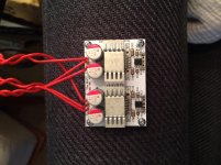
I think one of the heatsink was in contact with the amp output. I removed all 4 heatsinks and test again but same stuff. One channel is OK. The other is not, caps are getting very hot in no time and the trafo is buzzing.
I've noticed some solder on the positive output pad while no cable is soldered yet (visible on the pic above), maybe that ? Otherwise, I double checked all solder and seem OK.
I've noticed some solder on the positive output pad while no cable is soldered yet (visible on the pic above), maybe that ? Otherwise, I double checked all solder and seem OK.
With open/shorted inputs, shorting the output shouldn't increase current draw to the point of saturating the transformer as far as I know. Sounds like you're gonna have to grab the DMM and hunt for shorts (or just suspiciously low resistances; you have a working reference channel to compare your measurements to so that's quite handy) - you mentioned the caps (which ones?) getting hot, does anything else get hot? It's possible to fry MLCCs, I recently managed to do that on a pupDAC by being obsessive about getting perfect "machine-quality" joints and reheating/wicking one MLCC one time too many. Usually it's the active/semiconductor components (or bridges between their pins) causing shorts like that but passives can and do fail as well from time to time.
Another thing to watch out for is stray copper strands from multi-strand wire that may end up on the board when stripping wiring isolation. Those can be very hard to see and have a nasty tendency to end up somewhere well-hidden shorting supply and ground pins.
Also, what's that greyish thing between the two lower right pins on the upper op-amp? Looks a bit suspicious to me, but may just as well be an image artifact or something. Try taking some high-quality, well-lit pictures of both sides of the board and someone might be able to see what's going on.
I'd recommend reflowing all joints on the board and cleaning it real well (i.e. bathe it in isopropanol and give 'er hell with a toothbrush) afterwards anyway - some joints look rather scrawny. I can't see any obvious shorts on that pic though, but I also haven't seen the other side yet.
Last edited:
No no no!
Get the BAL-BAL, build it up exactly as per the BAL-BAL BOM, and the only thing that needs to change is the way you wire the inputs and outputs.
The inputs are wired as balanced inputs using XLR (or whatever else you might want) and the only difference is that instead of taking the output from + terminal to - terminal, you instead take the output from + terminal and run it back to GND at the PSU input on the BAL-BAL board. This allows to you to use the board with SE output, and also allows you to swap back to differential output if you ever feel the need. You could even wire it up with both a balanced jack, and a 3-pin SE jack and just use one or the other. Alternatively, you can have a pair of 3-pin jacks, and wire one up from the + terminals to GND, and the other from the -terminals to GND to get an inverted and non-inverted output.
Have fun!
Owen
Hi Owen,
Just finished my build (still unboxed) and starting to test it, first tried to use the SE output as described above—but with the difference that I'm using a Sep. PS for each channel. Voltage is stable, nothing got more than slightly warm (-30db signal being sent out)—but only hum on one channel and a click on the other (on connection). DC had approximately 56mv on either side (referenced to the ground) (0 mv coming from my source). Next I hooked a speaker up to first one, and then the other channel (using balanced outs), and there is music—much to my relief! So, my assumption is that since I've wired up two power supplies, the ground from one will not function as a SE ground for both, which in retrospect, makes sense.
But it also seems that the channel that the ground was viable for should have given me a clean signal, since I was not attaching a load to both channels at once, and trying to share the ground. This has me confused. Could it mean a problem on one (or both) of the + legs?
I'm still waiting for connectors for my headphones so I can finish my balanced cable—so I can't comment on sound quality—what I hear, one channel at a time, using crap headphones, by just touching the outs, sounds good.
It would be nice (but not necessary) to have a SE output; I also know it's not necessary for the dual PS either... But I guess if pushed, I'd give up the SE output. Is there a way to have both?
Just curious if there are any setbacks if I use the Wire PSU to power both a Wire SE-SE and the JG Buffer/Filter portion of Acko's AKD23P. The buffer/filter requires a small amount of current something like 30 or 40mA. It might even be less. They both will use ±15V. I suppose all I'd need to do is account for current requirements for both boards with regards to a transformer and that'd be it.
This is my goal as a streaming server / DAC / Amp all-in-one...
Beagle Bone Black (RuneOS) -> Acko Re-clocker/Isolator -> Acko AKD23P with JG Buffer -> Wire SE-SE. As a bonus I'd love to switch between an Amanero USB transport and the BBB i2s. Bonus+... to be able to have RCA outs as well so I can go to an alt. amp. Don't know if it's possible. But a man can dream.
Last edited:
^^ Given that a single PSU will power up the BAL BAL, I can’t imagine there’d be any current draw issues with powering up that portion of the DAC along with an SE board.
Just curious if there are any setbacks if I use the Wire PSU to power both a Wire SE-SE and the JG Buffer/Filter portion of Acko's AKD23P. The buffer/filter requires a small amount of current something like 30 or 40mA. It might even be less. They both will use ±15V. I suppose all I'd need to do is account for current requirements for both boards with regards to a transformer and that'd be it.
This is my goal as a streaming server / DAC / Amp all-in-one...
Beagle Bone Black (RuneOS) -> Acko Re-clocker/Isolator -> Acko AKD23P with JG Buffer -> Wire SE-SE. As a bonus I'd love to switch between an Amanero USB transport and the BBB i2s.
Can't see why not. I have the parts for a similar setup here but haven't got around to putting that together ... one of these days.
Bonus+... to be able to have RCA outs as well so I can go to an alt. amp. Don't know if it's possible. But a man can dream.
I asked a similar question and the response from opc is here I didn't get around to trying that out in that build.
ok so it's been a while since I have asked a question that I've felt is as stupid as the one I'm about to ask.
But ....
Tonight I'm in the garage testing a BAL-BAL.
First power up - less than 100mA on each rail of the PSU. Sweet.
Poke around, everything looks fine.
(Was trying to get a difference measurement on my shiny new Rigol DSO1054z scope to see the differential output but ... that measurement not working for me at the moment ... will worry about that later ... that is undoubtedly a user error)
So that all doesn't sound that stupid right?
Well now, I get to plugging in a DAC (via a RCA -> XLR cable) plug in my HD600 with genuine Senn balanced cable.
Now I'm getting output ... headphones didn't blow up ... yippee?
Hang on
The PSU isn't on yet.
What? 😱

That's not right Shirly.
With PSU on the amp does seem to work just fine (is louder than with no PSU attached). Left and Right channels both work.
Turn off PSU and disconnect PSU cable ... Still an output, not even particularly quiet. Left and right channels have the same behaviour.
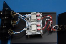
This is what the BAL-BAL looks like:

So dumb question why am I getting output when the BAL-BAL doesn't have a PSU connected?
diyATheWireThread's favorite curmudgeon (qusp) isn't even around these parts of the internet to give me grief about why I'm not seeing what is going on here.
So .... opc ?? AndrewT ?? Can someone tell me why I'm here asking a dumb question ... please?
Chris
But ....
Tonight I'm in the garage testing a BAL-BAL.
First power up - less than 100mA on each rail of the PSU. Sweet.
Poke around, everything looks fine.
(Was trying to get a difference measurement on my shiny new Rigol DSO1054z scope to see the differential output but ... that measurement not working for me at the moment ... will worry about that later ... that is undoubtedly a user error)
So that all doesn't sound that stupid right?
Well now, I get to plugging in a DAC (via a RCA -> XLR cable) plug in my HD600 with genuine Senn balanced cable.
Now I'm getting output ... headphones didn't blow up ... yippee?
Hang on
The PSU isn't on yet.
What? 😱
That's not right Shirly.
With PSU on the amp does seem to work just fine (is louder than with no PSU attached). Left and Right channels both work.
Turn off PSU and disconnect PSU cable ... Still an output, not even particularly quiet. Left and right channels have the same behaviour.
This is what the BAL-BAL looks like:
So dumb question why am I getting output when the BAL-BAL doesn't have a PSU connected?
diyATheWireThread's favorite curmudgeon (qusp) isn't even around these parts of the internet to give me grief about why I'm not seeing what is going on here.
So .... opc ?? AndrewT ?? Can someone tell me why I'm here asking a dumb question ... please?
Chris
Attachments
Hi Chris,
It's just the nature of the input resistor and feedback scheme on the differential amplifier.
If you look at the schematic, you'll notice the input connects directly to the output via the input resistors (1K) and the feedback resistors (1K) which means that when the power is off, your DAC is directly driving your headphones through a 2K resistor on each phase.
If you have very low impedance headphones you'll hardly be able to hear this, but with the 300 ohm impedance of the HD600, you will get appreciable voltage even with the pair of 2K loads in series.
In this setup, however, you have no current gain, and voltage gain should be in the order of -22dB from what the DAC is putting out.
Once you power up, then the voltage gain should be 0dB and you get access to the output current of the buffer.
I had a similar experience when testing a few years ago with the BAL-BAL. I unplugged it to go to bed, and still noticed it was playing. I thought "wow, that power supply is really holding a charge for longer than I would have though". After a few more minutes I got the DMM out and realized the rails were down to 0V and it was still playing. That's when I looked at the schematic and realized what was going on 🙂
I owe you an email, by the way, and I'll try to get that out this afternoon!
Glad you got everything up and running!
Cheers,
Owen
Hi Owen,
Well, that's certainly a relief! "Look at the schematic and think" ... what a novel concept ... 😀
The DAC I was using in that test was a QNKTC ES9022 but the USB converter in that forces OSX to use no digital attenuation so it was 0dBFS single ended signal. I only built one RCA->XLR cable was was listening mono ... don't ask me for listening impressions on mono headphone listening!!
No dramas with the email man, I've been busy and finally getting a bit of time for hobby projects now, which I'm happy about but a damn shame I had no time while the ambient temperatures were more reasonable (summer is ... unpleasant). I've finally got the second of the LPUHP monoblocks built, now to test them tomorrow night fed off this BAL-BAL. Will post some pics later in the week hopefully.
So now I've got to work out the correct setup for math config on my new DSO to look at the differtial output of the BAL-BAL.
Cheers,
Chris
Last edited:
Over 3 metre interconnects from DAC to power amp's, does going via the Bal-Bal, or a SE-SE, give a better sound?
The longer wires dull the sound compared to 3/4 metre ones. Does the low output impedance and current drive of the headphone amp bring the sound back to life?
Compared with going direct, DAC to amps, does adding the headphone amp add some degradation from the extra components, solder joints, tracks, connectors?
Last edited:
- Home
- Amplifiers
- Headphone Systems
- "The Wire" Ultra-High Performance Headphone Amplifier - PCB's