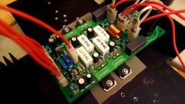
Single layer IPS 😀
The pdf please🙂Very cool


This has been a crazy ride. This morning I sat down and jotted down the voltage drop across each resistor and the vbe for each transistor. Q5 only had a vbe of .216V. I was ready to replace it but it measured perfectly with a diode test so I pulled the tube and replaced it with one from my Low TIM hybrid and all the voltages fell into line. I hooked it back up and still have some oscillation but simply clipping a length of wire onto the junction of R19, 20 & 21, causes the oscillation to almost completely disappear. This is on the board that has Q8,9,11&12 removed. So then I grab the other board that is still in stock form and install the same tube and it works perfectly. I tried shutting it down and restarting, with and without input attached or load and could not get it to oscillate. Square waves are the cleanest I've seen with any of my amps. Music sounds incredible.
So now I am puzzled as to why a couple of day ago this seeming good board was giving me so much grief. They do seem picky about what tube you use. I will be sending back the ones I bought recently as they evidently have issues and I have no way to test for it. I still need to find out why one board is so different than the other. I built them side by side and installed one component per board before moving on so they should be identical but for some reason they aren't.
Thanks for sticking with me. I'm almost out of the woods.
Blessings, Terry
Terry, I'm glad you stuck with it and seem to be getting this ips to work. This is definitely the next toy I want to play with.
Evan
Evan
Success!
I finally ironed it all out. Both IPS are back to the original circuit. I must apologize to Valery for all this trouble. It was my fault that things went this way. The final issue came down to oscillation in the OPS. I discovered it when I had finally got both boards to behave and I went to hook them up in stereo and the left channel was oscillating again,. That is when I remembered that I had only pulled the caps and installed the 680R gate stoppers in one channel so I could compare them. I never changed the other. As soon as I made the changes to the left channel OPS the oscillation issues went away. It was my fault because earlier I was lazy an rather than disconnecting the good IPS I just hooked up the troubled one to the left channel OPS which I know now, was the problem. It is playing music as I type this. Sounds very, very nice. I will post some pics of some sine waves and square waves in a few minutes.
Blessings, Terry
This has been a crazy ride. This morning I sat down and jotted down the voltage drop across each resistor and the vbe for each transistor. Q5 only had a vbe of .216V. I was ready to replace it but it measured perfectly with a diode test so I pulled the tube and replaced it with one from my Low TIM hybrid and all the voltages fell into line. I hooked it back up and still have some oscillation but simply clipping a length of wire onto the junction of R19, 20 & 21, causes the oscillation to almost completely disappear. This is on the board that has Q8,9,11&12 removed. So then I grab the other board that is still in stock form and install the same tube and it works perfectly. I tried shutting it down and restarting, with and without input attached or load and could not get it to oscillate. Square waves are the cleanest I've seen with any of my amps. Music sounds incredible.
So now I am puzzled as to why a couple of day ago this seeming good board was giving me so much grief. They do seem picky about what tube you use. I will be sending back the ones I bought recently as they evidently have issues and I have no way to test for it. I still need to find out why one board is so different than the other. I built them side by side and installed one component per board before moving on so they should be identical but for some reason they aren't.
Thanks for sticking with me. I'm almost out of the woods.
Blessings, Terry
Hi Terry,
This is definitely a very valuable information. So, we need to be careful with the tubes we use. There's a lot of manufacturers producing them - in fact, internal structure may differ, influencing capacitances, gain (to some extent), biasing, etc. Probably, we get some statistics over the time. Please remind me, what manufacturer re your tubes from?
I use Russian Electro-Harmonix ones - no issues, except one tube (out of 4) has got so big difference between the triodes, it can't be compensated by DC servo, so I've just put it aside.
Cheers,
Valery
Success!
I finally ironed it all out. Both IPS are back to the original circuit. I must apologize to Valery for all this trouble. It was my fault that things went this way. The final issue came down to oscillation in the OPS. I discovered it when I had finally got both boards to behave and I went to hook them up in stereo and the left channel was oscillating again,. That is when I remembered that I had only pulled the caps and installed the 680R gate stoppers in one channel so I could compare them. I never changed the other. As soon as I made the changes to the left channel OPS the oscillation issues went away. It was my fault because earlier I was lazy an rather than disconnecting the good IPS I just hooked up the troubled one to the left channel OPS which I know now, was the problem. It is playing music as I type this. Sounds very, very nice. I will post some pics of some sine waves and square waves in a few minutes.
Blessings, Terry
Congrats! Nice to hear
 😎
😎Should we be using matched tubes for this input?Hi Terry,
This is definitely a very valuable information. So, we need to be careful with the tubes we use. There's a lot of manufacturers producing them - in fact, internal structure may differ, influencing capacitances, gain (to some extent), biasing, etc. Probably, we get some statistics over the time. Please remind me, what manufacturer re your tubes from?
I use Russian Electro-Harmonix ones - no issues, except one tube (out of 4) has got so big difference between the triodes, it can't be compensated by DC servo, so I've just put it aside.
Cheers,
Valery
Hi Valery,
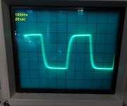
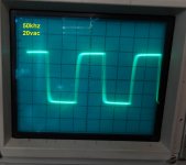
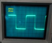
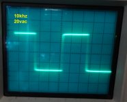
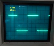
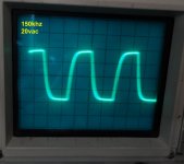
I may have spoken too soon I let it play for about a half an hour and then went out to take some pictures of the scope. I couldn't see any oscillation on the scope when music was playing but when I hooked the generator and dummy load so I could get the pictures I still have a little oscillation. I am really beginning to believe it is OPS related The only thing that changed since I tested it earlier is that the heatsink had warmed up. It only does it when there is a load attached. I took some pictures of some sine and square waves without the load attached for your viewing.
PS the tubes I bought for this amp are JJ electronics. I used those in the past in my guitar amps with good results. These are so far off the best the servo can do is 2.5V offset.
Do you think it mighet be good to add some caps to the OPS? If so, what value should I start with?
Thanks, Terry
Should we be using matched tubes for this input?
Well, matched triodes within the tube are always better for such a balanced input arrangement - the more equal they are, the less distortion and other issues they cause. The circuit is able to balance them out to some extent, but with certain limitations for sure.
Hi Valery,
I may have spoken too soon I let it play for about a half an hour and then went out to take some pictures of the scope. I couldn't see any oscillation on the scope when music was playing but when I hooked the generator and dummy load so I could get the pictures I still have a little oscillation. I am really beginning to believe it is OPS related The only thing that changed since I tested it earlier is that the heatsink had warmed up. It only does it when there is a load attached. I took some pictures of some sine and square waves without the load attached for your viewing.
PS the tubes I bought for this amp are JJ electronics. I used those in the past in my guitar amps with good results. These are so far off the best the servo can do is 2.5V offset.
Do you think it mighet be good to add some caps to the OPS? If so, what value should I start with?
Thanks, Terry
Well, this also may be something to do with different MOSFET manufacturers. When I started testing this setup with OPS for the very first time, I also had some "light" (around 1-1.5 V RMS) oscillation, coming from OPS. So, finally I use 470R gate stoppers and 220pF caps right on 2SK1058 G-D pins. In this configuration it is perfect. Try to start from this one and if it's still there - try to increase the caps value, adding by 100pF or so.
So the caps go across the gate/drain rather than the gate/source that the board are set up for?
Thanks, Terry
Thanks, Terry
So the caps go across the gate/drain rather than the gate/source that the board are set up for?
Thanks, Terry
That's right, gate-drain is the right position. I have changed it in the updated board layout, but initial one has it in a wrong way. So, better just put the caps right on transistor pins (side ones).
Sorry for confusion 🙄
Attachments
What Mosfet manufacturers are you using? I've got Renesas coming for mine.
I also think I use Renesas 😀
I also think I use Renesas 😀
Okay. I'm using Electro-Harmonix tubes as well so I should be good to go with the specs on the as built schematic then.
OK I think I finally have it. Now keep in mind that I have 470R gate stoppers on the J channel and 680R on the K channel. I first tried 220p across G-D on the 2SK1058's. It was better but still some fuzz on the top of the square waves. So then I tried 330p and it was worse. Then I tried 150p and it looks perfect. Now I can't say if the original 330p caps might have done the job with 470R on both sides because I just installed the caps in the holes provided. It is playing beautifully now. I will keep an eye on it for the next few days and make sure it doesn't start oscillating.
I used Renesas outputs too
Blessings, Terry
I used Renesas outputs too
Blessings, Terry
Last edited:
- Home
- Amplifiers
- Solid State
- Ultra-high performance, yet rather simple - hybrid and more!