I changed the K channel resistors to 680R and removed the caps. With high hopes I fired it up again with the Sumasui IPS. Still have oscillation so I hooked the CFA-XH ips back up and nos oscillation. So then I tried the Spooky and no oscillation. Next I hooked up the Low TIM hybrid and still no oscillation. So now I am even more confused. I guess I'm just too inexperienced do deal with this. I'm going to set it aside. Hopefully one of the guys who got boards from me will get theirs going.
Hi Valery,
Here's an update. I tested the Symasui on my Slewmaster with the vertical outputs and it shows oscillation there too so obviously I need to pursue that a little further so hooked up the Tubsumo IPS. It wouldn't come up all the way through the light bulb. It would only allow +-42V rails which would leave the offset at -32V. Plugging it into the wall would let it power all the way up however the bias is quite high. The lowest I can adjust the bias is 42mV across a pair of of 0R22 emitters. Anyway, I didn't see any oscillation on the sine wave at 1khz, even with a load. That was promising so I reconnected R36 and R37 to get back to square one. The sine wave looked ok so I tried a square wave. It looked OK for a few seconds and them I saw oscillation for a couple of seconds before R115 on the OPS smoked just before the - rail fuse blew. I don't know if this get you any closer to knowing what is going on but I thought I should share it just in case.
Blessigs, Terry
Hi Terry,
Just curious: have you done any testing with the BJT or FET input versions, or just with the tube front end?
Ray
Just curious: have you done any testing with the BJT or FET input versions, or just with the tube front end?
Ray
Hi Ray,
No, I intended to but I ran out of boards. If I can get this one figured out I will order some more. I have spent the past two hours trying to fix my OPS. I blew 6 outputs and it looks like some of the drivers and/or pre-drivers got hit too.
Blessings, Terry
No, I intended to but I ran out of boards. If I can get this one figured out I will order some more. I have spent the past two hours trying to fix my OPS. I blew 6 outputs and it looks like some of the drivers and/or pre-drivers got hit too.
Blessings, Terry
Hi Valery,
Here's an update. I tested the Symasui on my Slewmaster with the vertical outputs and it shows oscillation there too so obviously I need to pursue that a little further so hooked up the Tubsumo IPS. It wouldn't come up all the way through the light bulb. It would only allow +-42V rails which would leave the offset at -32V. Plugging it into the wall would let it power all the way up however the bias is quite high. The lowest I can adjust the bias is 42mV across a pair of of 0R22 emitters. Anyway, I didn't see any oscillation on the sine wave at 1khz, even with a load. That was promising so I reconnected R36 and R37 to get back to square one. The sine wave looked ok so I tried a square wave. It looked OK for a few seconds and them I saw oscillation for a couple of seconds before R115 on the OPS smoked just before the - rail fuse blew. I don't know if this get you any closer to knowing what is going on but I thought I should share it just in case.
Blessigs, Terry
Hi Terry,
+/-42V is too low for the tube to work properly - that's why the offset was so high.
R115 is a 10R one at the rail, right? Oscillation at high bias is dangerous - it was a "current shoot-though", when one side outputs have opened and the other side did not close yet.
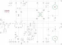
We can try to do the same thing as OS and Thimios just tested with Kypton-V, removing the super-pairs and the cascodes. Simulated performance is very close to original one, but this one is expected to be less "nervous".
It only requires some parts to be removed and two jumpers set at each side (positive and negative sides). Also, R29 has to be changed to 82R.
I will probably try this setup as well a bit later... although the original one is still playing here 😕
Cheers,
Valery
Attachments
Or, If you want to have the lower VAS current... with R29 = 100R it will be 5.5mA - much closer to most of the other IPS boards. However, for LatFet with direct connection it will be better to have it a bit higher (8mA with R29 = 82R).
Hi Valery,
I may try that tomorrow. Still don't understand why your is stable and I can't get mine there. It was better on the vertical FET OPS. May have been fine if I hadn't reconnected R36/37 but the bias was too high. I don't want to reinvent the wheel, just get it working. Thanks for sticking with me.
Blessings, Terry
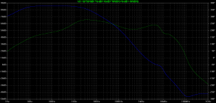
Vzaichenko, I try your compensation (TMC) to Kypton-V.
THD at hig frequency reduce and slew rate increase.
THD at 1kHz is the lowest amp that I ever sim 😎
Sorry, this is the right one 🙂
Attachments
Hi Valery,
OK this is what I've done.
I pulled Q8,9,11&12.
I jumpered C-E on Q11 & Q12 pads
I pulled R39 & R40
I replaced R29 with 82R
I'm not getting any signal on the output. I have 3.4V across R25 & R26 but only 1.4V drop across R32 & R33. Not sure what's going there.
It's late now so I will take some more measurements in the morning and mark up a schematic.
Hi Valery,
OK this is what I've done.
I pulled Q8,9,11&12.
I jumpered C-E on Q11 & Q12 pads
I pulled R39 & R40
I replaced R29 with 82R
I'm not getting any signal on the output. I have 3.4V across R25 & R26 but only 1.4V drop across R32 & R33. Not sure what's going there.
It's late now so I will take some more measurements in the morning and mark up a schematic.
Hi Terry,
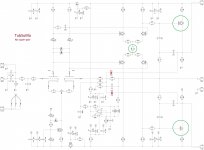
Another jumper has to go from the base of Q10 & Q13 to R34 and R35 respectively.
Also, additional caps C27 & C28 are not required - just forgot to remove them...
Cheers,
Valery
Attachments
Sorry, this is the right one 🙂
Hi Bimo, that's true - with TMC, output stage is also in the loop at HF, so when it is tuned right, TMC reduces distortion at the higher end and "speeds up" the whole circuit a bit

Hi Terry,
Another jumper has to go from the base of Q10 & Q13 to R34 and R35 respectively.
Also, additional caps C27 & C28 are not required - just forgot to remove them...
Cheers,
Valery
Sorry, I forgot to list those. They were installed as well.
Any idea why I have so much more current on Q4&5 than I do on Q6&7?
thanks, Terry
Sorry, this is the ...
Hi Anistardi (is that the correct form?)
Probe needs to be before tap for the TMC to analyse OPS stability.
You have it after (on the left), should be on the other side.
Your placement does reveal some useful information but the other placement is more likely to be the critical one.
This type of compensation is not easy to analyse, I definitely plan to include this in my next Linear Audio article.😉
There is probably more to be done, just a bit busy now.
Best wishes
David
If you also put the differential probe balun that I sent you, and place it at the inputs to the VAS transistors Q9 and Q10, that will reveal useful information too.
Valery's post #272 provide the reason why the probe placement needs to be altered.
Last edited:
Hi Anistardi (is that the correct form?)
Probe needs to be before tap for the TMC to analyse OPS stability.
You have it after (on the left), should be on the other side.
Your placement does reveal some useful information but the other placement is more likely to be the critical one.
This type of compensation is not easy to analyse, I definitely plan to include this in my next Linear Audio article.😉
There is probably more to be done, just a bit busy now.
Best wishes
David
If you also put the differential probe balun that I sent you, and place it at the inputs to the VAS transistors Q9 and Q10, that will reveal useful information too.
Valery's post #272 provide the reason why the probe placement needs to be altered.
OK, David. Next time I will try your probe.
For now, I revise my simulation file using Tian.
Phase Margin slightly increase and Gain Margin slightly decrease.
Attachments
Sorry, I forgot to list those. They were installed as well.
Any idea why I have so much more current on Q4&5 than I do on Q6&7?
thanks, Terry
Hi Terry,
Something is wrong. Those currents may differ a little bit, but in a way that the voltages over R25/26 and R32/33 are, say, 1.48V and 1.44V respectively. Your difference is huge. Are you sure the bases and the emitters of Q10 & Q13 are not swapped? Sorry, I'm coming up with crazy ideas 🙂
Voltages over R41/44 (100R) have to be around 0.7-0.8V (that gives VAS current 7-8mA respectively).
If everything looks fine in this area - let's see the voltages in the other places, like bases of Q4/5, Q6/7 (reference to ground).
Cheers,
Valery
Hi Valery,
Sorry I didn't get to it today. I spent what time I had fixing the vertical OPS. Drove me nuts trying to get working until I realized that 5 of the emitter resistors were open.
I'll sit down tomorrow and mark up a schematic with all the voltages on it. I guess I'll have to check the all the transistors for pinout. I just went with the devices called out in the schematic. I didn't think to check the layout.
Thanks again, Terry
- Home
- Amplifiers
- Solid State
- Ultra-high performance, yet rather simple - hybrid and more!