Yes, 14W is too low here! You need at least 3x or 5x.
For 4p1l filament bias you are looking for 30-40W!
For 4p1l filament bias you are looking for 30-40W!
If these are for filament bias, my recommendation would be TWICE the wattage - these resistors get hot. I would use some big vitreous enamel ones. My 4P1L PSE amp is on 24/7 and has been for a year and a half, and no pops.
Hi Andy, which one are you using in your 4P1L PSE ???
/Michael
I use some Dale surplus stock resistors I got of ebay USA for the input section. But I also use vitreous enamel ones - the bigger the better. You can parallel them up.
Funny thing, in the end it was a grounding problem not the resistors! 🙂
Idont believe you had a resistor problem here Michael, but I may also be wrong.
Just changed the resistor, problem gone 🙂
Next time the problem occurs I'll go with some 25W or even 50W...
LTSpice says that wattage required is max 2.8watt , so I thought 12watt
was enough , but maybe I should be more conservative 🙂
I use some Dale surplus stock resistors I got of ebay USA for the input section. But I also use vitreous enamel ones - the bigger the better. You can parallel them up.
Thanks Andy...
I know that you're not happy with the METAL ones, that for instance my good
friend bjarne (Beardman) is using...
I just need to reach a certain level of stability, then I can shop for some with better sound quality....
/Michael.
Yes, 14W is too low here! You need at least 3x or 5x.
For 4p1l filament bias you are looking for 30-40W!
seriously? i thought of getting 12w mills as in my previous 6e6p/6s19p build. 30-40w just looks crazy.. yes it is hot but it's not abnormal i guess
Member
Joined 2009
Paid Member
Linearity-wise the 6E5P looks to be comparable to the 4P1L - and much easier to arrange the heater supply - I expect there is more to the 'sound' than linearity but what makes the 4P1L a better choice ?
I've never found any indirectly heated tube that sounds like a directly heated tube. The closest was 2C22. To my ears they're worlds apart. I get transparency and dynamics, sort of a crystal like clarity with directly heated tubes, or at least the best of them. Makes indirectly heated tubes sound just slightly blurry, like cathode bypass caps make the sound slightly heavy and blurry. There is nothing to my ears that sounds like directly heated tubes with filament bias and no cathode bypass caps, and nothing that joins stages better than a really good interstage. You can especially hear it on vocals, but the clarity is there right across the board, and better timbre on acoustic instruments.
I am totally with Andy. Once you get hooked into the DH tubes can't ever go back...I tried and failed...��
Just right about the sound in the 4P1L,,very hard to get any better--
i use 50w mills ,they are in cooling house,,and i have mounted them on my 5mm alu top plate...so they are cooled very fine,,,and no pops
Best Bjarne
i use 50w mills ,they are in cooling house,,and i have mounted them on my 5mm alu top plate...so they are cooled very fine,,,and no pops
Best Bjarne
I have build a couple of 4P1L for my friends, but this morning, my friend and I have those "microphonic pops" from both our amps.
PS! This is very weird. The two Mills from my Friends Amp was measured at exactly 8.2 Ohm , which I replace with two Ohmite with exactly 8.2 ohm, his solved the problems with those "extreme pops".
If these are for filament bias, my recommendation would be TWICE the wattage - these resistors get hot. I would use some big vitreous enamel ones. My 4P1L PSE amp is on 24/7 and has been for a year and a half, and no pops.
Just changed the resistor, problem gone 🙂
I think the problem might be related to the connections to the resistors - either the solder joints or the connections between the resistor body and the external wires. The popping noise that Michael describes sounds similar to problems that I've had with bad solder joints in other projects.
It's become known recently in computer PCBs that the combination of high current and high temperature can cause premature failure of solder joints. Think about a typical Intel processor in a laptop - it can easily consume 40W. The power supply for the process is between 1v and 1.5v, meaning that peak current consumption can be >25A! If you search for high temperature high current solder bump failure, you will find many articles. The key messages that I take away from that work are the following.
- Failure rate is strongly dependent on temperature, so make sure your resistors don't get too hot.
- Connections that depend on only the solder to hold the joint together are more prone to failure. So make sure that you have a good mechanical connection before soldering.
- Stress can accelerate failure. The expansion/contraction during heating and cooling can add to the stress.
- Make sure your connections to the resistors aren't stressed. Use wires that have a bit of flex to them. For resistors with wire end connections, think about putting a loop in the wire so that the resistors can move freely as they heat up or cool down.
- The melting point of the solder can also affect things. Lead free solders (Sn/Ag or Sn/Ag/Cu) have higher melting points than traditional Pb/Sn solder and with all other things being equal will be less susceptible to this effect. But this will be a 2nd order effect compared to the others.
Note that I haven't built my own 4P1L project so these comments are extrapolated from things that I've learned elsewhere, which means that the comments are a bit speculative.
---Gary
Last edited:
I think the problem might be related to the connections to the resistors - either the solder joints or the connections between the resistor body and the external wires. The popping noise that Michael describes sounds similar to problems that I've had with bad solder joints in other projects.
It's become known recently in computer PCBs that the combination of high current and high temperature can cause premature failure of solder joints. Think about a typical Intel processor in a laptop - it can easily consume 40W. The power supply for the process is between 1v and 1.5v, meaning that peak current consumption can be >25A! If you search for high temperature high current solder bump failure, you will find many articles. The key messages that I take away from that work are the following.
- Failure rate is strongly dependent on temperature, so make sure your resistors don't get too hot.
- Connections that depend on only the solder to hold the joint together are more prone to failure. So make sure that you have a good mechanical connection before soldering.
- Stress can accelerate failure. The expansion/contraction during heating and cooling can add to the stress.
- Make sure your connections to the resistors aren't stressed. Use wires that have a bit of flex to them. For resistors with wire end connections, think about putting a loop in the wire so that the resistors can move freely as they heat up or cool down.
- The melting point of the solder can also affect things. Lead free solders (Sn/Ag or Sn/Ag/Cu) have higher melting points than traditional Pb/Sn solder and with all other things being equal will be less susceptible to this effect. But this will be a 2nd order effect compared to the others.
Note that I haven't built my own 4P1L project so these comments are extrapolated from things that I've learned elsewhere, which means that the comments are a bit speculative.
---Gary
Hi Gary...
Not sure about that. This happend to two different amps within a couple
of days.
But now I have a 25w "Metal Vishay" in mine. If this "survives" for more than
the standard 3 month in mine, it was just a matter of going up in wattage..
We have to be a little patient , but I'm running a week 24/7 just to see If I can provoke anything.
/Michael.
i use 50w mills ,they are in cooling house,,and i have mounted them on my 5mm alu top plate...so they are cooled very fine,,,and no pops
Best Bjarne
Ah yes - forgot that. I always mount the resistors on the top plate to help with cooling. They really do get hot. Agree on a thick top plate - mass is very good for cutting down on resonances.
....... 50w mills ,they are in cooling house,,and i have mounted them on my 5mm alu top plate....
Best Bjarne
Photo please?
I remember one member that used the filament of indirectly heated valves for filament bias. Someone else did try, and compare?
Last edited:
Yes, Erik,
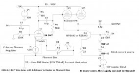
It was my design-suggestion for adding a cathode follower.
A low cost alternative for a cable-driver.
The IDHT cathode follower has its heater fed from the filament current of the 4P1L (etc); the 4P1L bias is developed from the IDHT heater.
I don't know if it has been tried.
It was my design-suggestion for adding a cathode follower.
A low cost alternative for a cable-driver.
The IDHT cathode follower has its heater fed from the filament current of the 4P1L (etc); the 4P1L bias is developed from the IDHT heater.
I don't know if it has been tried.
Attachments
Hi Rod,
indeed, yours was one! But I remember someone else as well who built a RIAA stage with indirectly heated tubes, and lit those up with a filament bias circuit.
I am working on a "raven style" preamp/headphone amp with the 4P1L, using cascoded TIP125s as CCS for the cathodes and biasing the whole with a 9V battery. I am thinking about filament bias using the filament of a 6P15P, which I want to use in a shunt regulator arrangement for the B+.
best regards, Erik
Photo please?
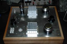
Little OFF...not exactly 4P1L...but also heater bias (#26).
I use large passive CPU heat sink as cooler. 10R (1..1.1 A) 50W DALE dissipates about 10W, after few hours heat sink temperature only 45-50 C grade.
Attachments

I use the heaters of my riaa preamp, 6p45 into 6e5p with current matching resistors as the filiment bias. In theory it should be noisier than over spect resistors but is quiet as long as you use good quality valve bases as any corrosion causes pops and farts till you wiggle the novel tubes about a bit!
P.s I used a 12av5 heater to bias 4p1l driver in my 300b amp as I didn't have the required resistor to hand too, still there a year later.
P.s I used a 12av5 heater to bias 4p1l driver in my 300b amp as I didn't have the required resistor to hand too, still there a year later.
Hi Enzoastro,
Thanks for your comment! So I will move ahead and try the 6P15P - I have some good sockets for them.
And indeed, I have way more tubes than power resistors in my stash, so there will always be an appropriate one to burn away the volts generated by filament bias.
thanks, Erik
Thanks for your comment! So I will move ahead and try the 6P15P - I have some good sockets for them.
And indeed, I have way more tubes than power resistors in my stash, so there will always be an appropriate one to burn away the volts generated by filament bias.
thanks, Erik
- Home
- Amplifiers
- Tubes / Valves
- 4P1L DHT Line Stage