There may be something wrong in your measurement, since 2JS109 V have maximum Idss of 20mA.
You are right, I measure my small stash of 8 duals 109BL-V grade and only one V grade is good and measure Idss 21,4mA😡 so I can't use because I need minimum 2 duals to make a stereo buffer.
Last edited:
Calvin BF256C data sheets max Idss 18mA isn't enough?
Please anybody can help me, a local store have on stock.
TIA
Last edited:
Please anybody can help me, a local store have on stock.
TIA
As Calvin wrote in post #352 and in other posts, the drain current Idss can be between 50mA and 150mA. So, no, Idss of 18mA isn't enough.
Hi,
the graph in #352 is characteristic for all JFETs.
To evaluate if Your candidate is suitable for the cascoding task have a look in the datasheets and the graphs.
If the DS contains only specs but no graphs, then you can estimate the Vgs at a certain Id in a first aproximation by drawing a straight line in a Id over Vgs graph instead of the real bowed curve.
The end points of the line beeing the Idss value at Vgs=0 and the Id value at Vgs(off).
If the result at a Id of ~8mA is less than -3V Vgs then the JFET should be fine for the task.
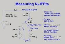
Attached is a easy schem how You can determine the critical values Yourself.
V1 may be a constant voltage power supply or a battery.
Rd is s measuring resistor to determine the drain current.
Choose V1 and Rd so that V(a) is similar to the idle working point of the later application.
A value around 9V suits best.
Vg is a variable negative voltage source. If You only have a constant negative supply at hand You may connect a 1Meg Poti from Vneg to gnd , the wiper going to the Gate.
Rs may be made from fixed resistors or a 1Meg Poti connected as variable resistor.
Following the instructions You can evaluate Idss, Vgs(off) and the Id versus Vgs behaviour.
As the manufacturing process of JFETs includes rather high tolerances the Values of Idss and Vgs(off) vary over a large range.
Manufacturers apply preselection into 2-or 3 Idss classes.
This preselection may already be good enough, as the value of Vgs of the cascoding JFET plays only a minor role for the output offset of the circuit.
Values of Vgs +-0.5V are still fine.
But if You want to achieve lower Vgs tolerances this easy screening method will suffice.
jau
Calvin
Calvin in your schematic the voltage aplied to the Gate is positive, I guess have to be negative?
gracies
Felip

Hi,
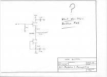
Can someone suggest a link ' where I could find full schematic od the Calvin buffer , with parts value ' zobel and output coil.
Can someone suggest a link ' where I could find full schematic od the Calvin buffer , with parts value ' zobel and output coil.
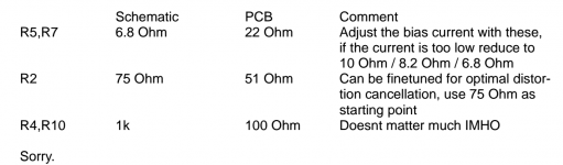
In the section of the Calvin buffer assembly guide shown below, it mentions R5 and R7 control the bias of what I assume is the output devices and can be from 22 ohms down to 6.8 ohms.
So I have a few questions:
1) Do I just pick a value like 6.8 ohms and measure the voltage drop across it to determine the current?
2) What should this current be?
3) When matching the JFET's, is there a certain value(or minimum value) Idss that I should be looking for if using the PF5102 and J107?
4) Can R4 and R10 be any value between 100-1K ohms like shown in the assembly guide, or does it really matter?
Thanks...
Attachments
Could I use JFET MMBF4391 Compre Transistores JFET Transistor JFET, MMBF4391, N-Canal, 12 mA, 0,4 V, SOT-23, 3-Pines Fairchild Semiconductor MMBF4391 en RS Online y lo recibir en 24 horas. in place of SST4391?
Could you answer some questions asked in your attached schematic?
TIA
Felipe
Please help.
Attachments
Could I use JFET MMBF4391 Compre Transistores JFET Transistor JFET, MMBF4391, N-Canal, 12 mA, 0,4 V, SOT-23, 3-Pines Fairchild Semiconductor MMBF4391 en RS Online y lo recibir en 24 horas. in place of SST4391?
Please help?
Just to point out MMBF4391 from Fairchild is not the same ( read much worse) then PN4391 from Vishay
Vds is only 30V , gate leakage currently is much worse , lack of info about noise
Noisewise best combo would be 2sk170/PN4319 Vishay
The problem is both devices are hard to get 🙁
Vds is only 30V , gate leakage currently is much worse , lack of info about noise
Noisewise best combo would be 2sk170/PN4319 Vishay
The problem is both devices are hard to get 🙁
I have a 20 years old tube preamp, which has a tape out buffer designed by John Curl.
Feeding this buffer from IVC (Inductive Volume Control) is the most transparent 'preamp' I ever heard.
Meanwhile source PN4391, I make it the JC's buffer and used with AVC of Intact Audio, you are right sounds very transparent.
N.B. Still waiting to source trough-hole njfets
Attachments
Joshua or Merlin, did you use the BL grade 2SK389 or another grade for the tape buffer?
Thanks...
Thanks...
Meanwhile source PN4391, I make it the JC's buffer and used with AVC of Intact Audio, you are right sounds very transparent.
N.B. Still waiting to source trough-hole njfets
Well, Felipe, you amaze me!
The reason I intend to build few buffer versions is that I purchased Tribute IVC module.
I tried it on my setup, replacing my preamp (Audible Illusions Modulus 3).
The purity and transparency of the sound was exemplary, something I never heard before. Alas, the dynamics went down. My power amp is Pass Labs XA30.5, with input impedance of 20KOhm.
My preamp has a tape out, constructed of… *JC's buffer!*
In testing to restore the dynamics, I connected the source to the IVC's input, the IVC's output to one of the inputs on my preamp, and the tape out of the preamp to the power amp.
The chain is now: source -> IVC -> JC's buffer -> power amp, at the 'cost' of 1 extra interconnect cable and 2 extra RCA sockets pairs in the chain. The 'cost' is possible impact of the extra components on the SQ.
Now I have the best of all worlds! Even with the 'elongated' chain. Everything is better (than my previous preamp) and exemplary: purity of sound, transparency and dynamics.
Yes, even the dynamics is better than my previous preamp, which I liked very much, until I heard the IVC buffered.
So, I'd like to have a buffer with the best possible SQ (on my existing setup).
So I'm going to compare 3 buffers:
1. JC's buffer (with 2SK170Vs).
2. Calvin Buffer SE Hybrid Cascode Compound.
3. Calvin Buffer PP Hybrid Cascode Compound.
All 3 will be fed from a PSU consisting of E-I power transformer, ultra-fast recovery diodes, choke input – followed by dual-mono Jung-Didden Super-Regulators.
The reason I went to such extent with the power supply is that I want to make sure that whatever differences in the SQ there may be, they wouldn't be out of any incompetency of the power supply.
Last edited:
Joshua or Merlin, did you use the BL grade 2SK389 or another grade for the tape buffer?
Thanks...
On my preamp there are 2SK389Vs. Alas, I don't have 2SK389s of any grade, so I'm going to use matched 2SK170Vs, thermally attached with Euval's mini-heatsinks.
- Home
- Source & Line
- Analog Line Level
- Preamp-Buffers - simple idea