Shoot, I had assumed you already knew about all the Baxandall stuff, otherwise I would have filled you in. I wondered why you weren't already all over it. Oh well.
Who , me ? I am a Lazy dog , and I'm busy chasing cats ... 😀
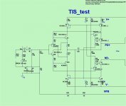
But , the TIS/CFA works (below) ! Time for further refinements.
OS
Attachments
Also don't forget about this:
http://www.diyaudio.com/forums/solid-state/210007-182mhz-oscillations-0-a.html#post2969744
http://www.diyaudio.com/forums/solid-state/210007-182mhz-oscillations-0-a.html#post2969744
TIS CFA and VFA
Works better as a VFA - nothing impressive as a CFA.
Lower gain TIS can't manage <10 ppm 20K as a CFA. PSRR blows at <70db.
But , it did work. Can't match the K-C @ 80+db psrr /8ppm 20k.
As a VFA (like the original concept), it is better. I managed <10ppm 20K and
it had typical VFA PSRR.
Perhaps as I did not use ideal CCS's / Ideal output stages , my results
were not as stellar. ??? 🙁
With that many parts , not enough "bang for the buck".
OS
Thanks, so the code number is SK....?hi thimios, yes that heatsinks are from fischer-elektronik. rth = 0.34*C/W
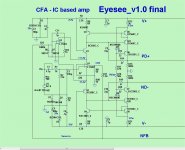
Eyesee is done - (design)
A perfect chip magnifier.
I read the TL072 paper .... 16V slew / .01% thd - eyesee w/ the TL does
32V slew and .01% 20K.
Just about every IC I simulated was within range of it's manufacturer's specs.
(or a little better). 🙂
IC is not in any compensation loop or directly in a feedback loop ,
therefore .... NO chip will exhibit any significant change in phase margin.
Some have higher native gain (higher CLG in the eyesee = .005% @ 20k).
The IC's spec is the only slew limiting factor - a faster IC = a faster amp ...
period.
OS
Attachments
So you dont use baxandall super-pair ?
It is not possible to use folded cascode ?
It is not possible to use folded cascode ?
Last edited:
And very easy to define/control the TIS standing current.One benefit to a very low-gain (1-3) TIS is that it can easier to make a very smooth clipping amp.
Cheers, E.
[..]
I assume, it also maintains common-mode stability, although I don't understand how, as yet. Need to do more thinking 🙂
Or, if Edmund Stuart would explain - I would very much appreciate it 😉
Don't know exactly what you mean by "common-mode stability". Perhaps stability of the TIS standing current (DC operating point) under dynamic conditions?
Please explain.
Cheers, E.
Don't know exactly what you mean by "common-mode stability". Perhaps stability of the TIS standing current (DC operating point) under dynamic conditions?
Please explain.
Cheers, E.
That's right - in such configurations, having two LTPs with CCS-ed tails and dynamic loads, in many cases "VAS competition" takes place, resulting in standing current fluctuation. CMCL is one of the solutions, however, in your super TIS something else ensures DC operating point stability (I believe). Right?
That's right - in such configurations, having two LTPs with CCS-ed tails and dynamic loads, in many cases "VAS competition" takes place, resulting in standing current fluctuation. CMCL is one of the solutions, however, in your super TIS something else ensures DC operating point stability (I believe). Right?
Right! The TIS standing current is simply defined by and equal to the LTP tail current. As for "VAS competition", this is absent for two reason;
1. Input inclusive compensation, so there are no two (slightly different) caps to the upper and lower TIS input, which might provoke fighting.
2. Unity gain of the TISes. So if ordinary Miller compensations was used (i.e. with two caps), even then there was no "VAS competition".
Cheers, E.
PS: The crux is that the gain of the TIS has been moved to the next stage, i.e. the pre-driver. This way a lot of trouble is circumvented.
Last edited:
Right! The TIS standing current is simply defined by and equal to the LTP tail current. As for "VAS competition", this is absent for two reason;
1. Input inclusive compensation, so there are no two (slightly different) caps to the upper and lower TIS input, which might provoke fighting.
2. Unity gain of the TISes. So if ordinary Miller compensations was used (i.e. with two caps), even then there was no "VAS competition".
Cheers, E.
PS: The crux is that the gain of the TIS has been moved to the next stage, i.e. the pre-driver. This way a lot of trouble is circumvented.
I see now! Edmond - thanks a lot for explanation, cool "out of the box" approach

Cheers,
Valery
Try the LT1057 🙂 It's currently LT's defacto standard hi-speed JFET generic opamp which is supposed to replace any earlier types (according to the datasheet). I'm using it in my schematic both as inverting input driver (2 of them) and as DC servo. It's THD is just 10ppb, completely neglible when loaded > 500R, at unity gain. But as it wouldn't affect your circuit other than slew, it probably won't matter much.A perfect chip magnifier.
I read the TL072 paper .... 16V slew / .01% thd - eyesee w/ the TL does
32V slew and .01% 20K.
Just about every IC I simulated was within range of it's manufacturer's specs.
(or a little better). 🙂
But I've declared it the generic opamp to use for myself (unless you want to go with audiophylic opamps).
if you use matched dual's for the mirrors I'am not so sure you really need a servo if you choose a trim-able op-amp.(as you have blocked input with a cap)
In the blowtorch thread there has been a debate about the performance of highly loaded op-amps, some maintains good performance even loaded down to 100 ohms
In the blowtorch thread there has been a debate about the performance of highly loaded op-amps, some maintains good performance even loaded down to 100 ohms
Try the LT1057 🙂 It's currently LT's defacto standard hi-speed JFET generic opamp which is supposed to replace any earlier types (according to the datasheet). I'm using it in my schematic both as inverting input driver (2 of them) and as DC servo. It's THD is just 10ppb, completely neglible when loaded > 500R, at unity gain. But as it wouldn't affect your circuit other than slew, it probably won't matter much.
But I've declared it the generic opamp to use for myself (unless you want to go with audiophylic opamps).
LT1057 is very good.
About twice as good as the LT1007 (below).
For CFA , you need more load - I used 112R ... but the IC is only <4V
(as a buffer). .005% is not too bad for such a simple circuit @ 20k.
OS
Attachments

I think I may have found a glitch with the 5 pair slewmaster with a Symasui input board. I had a pair of them idling on my new heatsinks for a couple hours yesterday. I shut them down and restarted then a couple minutes later and one channel immediately blew the rail fuses. Blew all the PNP outputs and the driver. I replaced the output board this morning and swapped the input boards, then fired it up again. After a couple hour I restarted it. I have 4 volts DC tapering off to nothing for 30 seconds after restart. I've restarted it a couple times since with the same result. Heat sinks are at 100F. Outputs are at 108F. Nothing hot. 15mV on the RE resistors.
ne5532 / tl072/ any dual 8-pin op-amp. Only the device idle current draw will
determine what ratio to set the wilson mirror to.
Most are 1.8 - 2.5ma (per op-amp).
OS
determine what ratio to set the wilson mirror to.
Most are 1.8 - 2.5ma (per op-amp).
OS
Last edited:
I have 4 volts DC tapering off to nothing for 30 seconds after restart.
Symasui uses a servo. Does the other one do it ?
OS
Last edited:
I'll check my Symasui 'restart' behaviour later this evening. I only have the 2P OPS with MOSFETs (or the Mini LMOS) handy for testing at the moment but I can see how it behaves. I'm sure I have done numerous start-ups and shut-downs on various IPS and OPS combinations and always found them to be pretty benign (no thumps, plops or sqealing etc.).
- Home
- Amplifiers
- Solid State
- Slewmaster - CFA vs. VFA "Rumble"