Both channel do it. They are almost identical in voltage and taper off. I have a pair of No GNFB tube inputs ready to connect. I'm going to leave these idle for the rest of the day and see what the tube inputs do tonight.
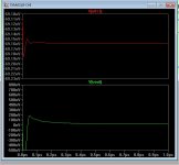
Reduce C12 to .22u. I did see <100mS servo settling time with delaycycle=0
on the simulator.
OS
on the simulator.
OS
Reduce C12 to .22u. I did see <100mS servo settling time with delaycycle=0
on the simulator.
OS
Leave C13 as is? I'll do one channel then compare.
Now it's only slightly quicker to settle. Still at almost 2 volts when the speaker relays engage.
Leave C13 as is? I'll do one channel then compare.
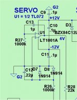
C13 is the main integrator (VERY crucial) C12 is the pre-filter from output.
Also , what IC for U1 ? (tl072?)
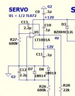
Actually , look (below) ... this is my standard non-inverting servo at present.
1meg/.22u/1meg/ 1u ...
For servo safety , you could also increase the servo output resistance to
68K (R28) for this VFA. Then a servo failure would be <2V at output.
PS - I would hard solder my servo in .At >1M input Z.. a socket high resistance point could be trouble.
EDIT - just a little flux on the IC pins or contamination in/on the socket would disrupt the high Z servo feedback.
It should settle INSTANTLY ! NP precision caps are the best for this circuit (no flux).
OS
Attachments
Last edited:
I'm using TL072. Would it be wise to change all the values to match this schematic? My C13 is 2.2uF and 680k sample resistors. I plan to direct solder my finished product amp. This is just a tester. But I did use good quality sockets. Worth 4 times as much as the op amps
I may be way off in left field here but I have a suspicion that the rail voltage may be coming up slower in one side then the other. I'll play with that tonight.
If you are 'just idling' these, do you have the inputs terminated into a source or just open? If they are open, does it behave any different with the input shorted?
I have the inputs shorted. I've decreased the idle current slightly and it doesn't trip the protection relays any more.
I have the inputs shorted. I've decreased the idle current slightly and it doesn't trip the protection relays any more.
Do you also have no load on the output? What do you think caused the output devices to blow? I have had huge offsets in the past without any damaged parts. Of course there was no load attached at the time.
I',m attaching small schematic of the servo section for the Symasui. What parts need to be changed to "fix" it?
Thanks, Terry
Attachments
I have the inputs shorted. I've decreased the idle current slightly and it doesn't trip the protection relays any more.
I made a mistake - R28 is best kept <39K (with a open input).
That is strange for your input ,C1 decouples the input from R2 (what sets
the ground reference for the LTP. NFB and R2 both get the "lifted ground"
reference , the servo reference (R27) goes to G2.
Either you have a "dirty ground" from what you hooked up..
Jumper R3 (lift resistor) and see what happens ??
OS
Both 12 rails come up fairly quickly. The negative rail lags slightly (1/4 second) but that may be the sampling time on my meters. They level off at 12 volts' then after a minute they creep up to 12.2 volts. Do I have a little too much current, warming up the zeners? 64 volt main rails. 61.5 volts after the cap multipliers.
Do you also have no load on the output? What do you think caused the output devices to blow? I have had huge offsets in the past without any damaged parts. Of course there was no load attached at the time.
I',m attaching small schematic of the servo section for the Symasui. What parts need to be changed to "fix" it?
Thanks, Terry
Is yours broken , too ?
OS
Is yours broken , too ?
OS
Not that I know of. I had no issues but I never tried switching it off and on quickly. Mine seemed issue free.
EDIT: When I said I had huge offsets with no damage I wasn't referring to this amp.
Last edited:
Both 12 rails come up fairly quickly. The negative rail lags slightly (1/4 second) but that may be the sampling time on my meters. They level off at 12 volts' then after a minute they creep up to 12.2 volts. Do I have a little too much current, warming up the zeners? 64 volt main rails. 61.5 volts after the cap multipliers.
4.7k works real good at 75V rails ...3.3K- 3.9K might be better for the 60V range. Decoupling caps settle quicker with more current.
OS
I made a mistake - R28 is best kept <39K (with a open input).
That is strange for your input ,C1 decouples the input from R2 (what sets
the ground reference for the LTP. NFB and R2 both get the "lifted ground"
reference , the servo reference (R27) goes to G2.
Either you have a "dirty ground" from what you hooked up..
Jumper R3 (lift resistor) and see what happens ??
OS
My R28 is 22k. I'll lift R3.
Terry, post 5013 is the "kypton" servo. With higher Z (1M/.22u/1M/1u).
But , if it ain't broke ... why fix it (your choice) ?
OS
But , if it ain't broke ... why fix it (your choice) ?
OS
My R28 is 22k. I'll lift R3.
Don't lift it - jumper it. It is the main reference. 😱
Edit - what I meant was that R3 WAS the lift resistor - not to "lift it" !
OS
Do you also have no load on the output? What do you think caused the output devices to blow? I have had huge offsets in the past without any damaged parts. Of course there was no load attached at the time.
I',m attaching small schematic of the servo section for the Symasui. What parts need to be changed to "fix" it?
Thanks, Terry
I killed an output board last night but I think it may have been a bad driver or predriver that set it off. It was idling a strangely before it failed. I haven't attached a load yet.
- Home
- Amplifiers
- Solid State
- Slewmaster - CFA vs. VFA "Rumble"