The valve amp was a very hot biased class AB and the SS one was a regular class AB.
I still think it is comparing like with like, as solid-state doesn't need Class-A to achieve better performance than any valve amp.
Also I showed with a distortion analyser that the SS amp was still successfully rejecting interference from the power supply while putting out its rated power. This is of course thanks to the evils/wonders of global feedback. 🙂
Charging transients may well be visible when probing grounds with a scope, but the real issue is whether they show up in the residual output of the distortion analyser.
They certainly do since they appear as audible buzz on the output. This buzz is not coming through the well filtered rails and as I said that makes it all but impossible to get rid of without a complete redesign.
I don't want to get into a long discussion about subjective vs objective performance but I would say that my best valve amps are as good as my class A SS and they sound equally as good - apart from the small residual buzz in the SS.
Shoog
Fourier analysis says nothing of the sort, it simply says that the more abrupt the turnoff, the more high frequency energy will be generated, and the higher the frequency content of it. There are purpose-built step recovery diodes that can generate energy up to 10s of GHz.
As I said before, if you have a sharp turn off that only occurs at infrequent intervals, there cannot be much energy generated by the sharp turn off. That's what Fourier says, and it's what common sense should tell you.
If you have, say, 1 nanosecond turn off & turn on at 2 nanosecond intervals, and 1 volt fed in, then you have almost all the energy in a 0.5 GHz frequency, ~1 volt. But if you have 1 nanosecond turn off & turn on at 20 mSec intervals, then yes with 1 watt going in you have some 0.5 GHz there still, but it is in the vicinity of 1 nanovolt. You''l have about 0.7 V at 50 Hz, 0.2 V at 150 Hz, 0.06 V at 250 Hz and so on...
I can't for the life of me imagine why on earth you would want to use a step recovery diode as a 50 /60Hz power rectifier, but if you did it won't change the picture much. Sure the harmonics will extend further up in frequency, but in the 100's of MHz region they will still be down in the 10^-9 region.
The 1/3 times reduction each time you go up one more odd harmonic, starting at the fundamental, is well known to all those who learnt Fourier at college or uni or wherever. Fourier does say the faster the transistion the higher the harmonics go, right enough, but Fourier DOES NOT say the higher the content in the sense that you implied. If it did, we could have more energy out than what went in (we must still have the fundamental) - we could have perpetual motion machines!
Last edited:
I would say that my best valve amps are as good as my class A SS and they sound equally as good - apart from the small residual buzz in the SS.
I have the same opinion except in my case it was the valve amps that buzzed and the SS ones that didn't. 🙂
This is true considering energy integrated over the whole period. But it is a known fact that rectifier diodes operating at line frequency can generate enough RF to fail an EMC test.if you have a sharp turn off that only occurs at infrequent intervals, there cannot be much energy generated by the sharp turn off.
EMI analysers use a quasi-peak detector that weights peak amplitude more heavily than average. This is supposed to simulate the subjective annoyance of radio interference, and I would argue that it has something to do with the subjective annoyance of breakthrough into the audio path too.
The natural recovery of rectifiers is more like a step. You have to deliberately make it soft by extra semiconductor processing. (FREDs etc)
Energy level of radio frequency interference and its harmonics is a bit of a red herring since when we get out to 10KHz + the energy levels are tiny compared to the main sub 100hz signals - and they are extremely audible. Tiny signals can completely ruin the subjective perception of the music. Rectifier artifacts can easily reach comparable energy levels to the high frequency signal components - especially when ordinary rectifiers and big caps are employed.
Change out an ordinary rectifier for a soft recovery type and its not difficult to hear the difference in most instances.
Shoog
Change out an ordinary rectifier for a soft recovery type and its not difficult to hear the difference in most instances.
Shoog
Last edited:
The natural recovery of rectifiers is more like a step. You have to deliberately make it soft by extra semiconductor processing. (FREDs etc)
Yes, certainly. But I have explained why the energy at high RF frequencies is vanishingly small, even if the recovery could occur in zero time.
Trobbins in his Post 4 included a link to another thread that supports his reasonable contention that as they are not intened to carry DC, performance is likey to be poor.
Hooly dooly Keit - wrong on all counts.
And then the temerity to finish off your post:
Others then chose to misrepresent what I said.
Hooly dooly Keit - wrong on all counts.
Sorry, it was Elvee in Post 2, not you. My bad alright. But it doesn't change the big picture. I made certain statements and others chose to misrepresent them.
Energy level of radio frequency interference and its harmonics is a bit of a red herring since when we get out to 10KHz + the energy levels are tiny compared to the main sub 100hz signals -
Change out an ordinary rectifier for a soft recovery type and its not difficult to hear the difference in most instances.
Shoog
I support that you can have trouble with noise, harmonics, etc within the audio band - I said that right from the start.
Therers another way to understand why the energy at high RF can only be very low with abrupt recovery, if you think there is something dubious about integrating over the whole period of 100 Hz:-
Imagine a square wave supplying 1 watt with a fundamental frequency of 100 Hz. That's an energy of 1 Joule per second, or 0.01 joul per cycle. Further, let's say the turn on and turn off time is 0.1 microsec.
Now, lets assume the turn-off is somehow improved to zero time. The difference in the area under the curve of the two waveforms is in a triangle of area in the proportion of 0.1 uSec : 10 mSec, i.e., 1:100,000, and this tiny tiny area is all that is available to generate the extra RF frequencies. So the extra RF generated by the zero time turn-off is 100 dB down.
There's not much value in going on about signals at GHz frequencies being similarly down in level. Yes, they are, for radio reception. We aren't discussing in this forum devices specificaly designed to receive radio signals at GHz frequencies - we are discussing tube-based audio amplifiers, which with their large gid base cf transistor inputs are not so susceptable to cross modulation.
In any case, low noise inputs in tube amps are gnerally implemented with triodes, whose miller effect from the grid-plate capacitance begins to roll off response not much above the audio band. A triode not having its strays tuned out with external L has no hope of responding to VHF or UHF frequencies. Pentodes have a lot less grid-plate capacitance, but that only takes you up to MHz frequencies unless special care is taken.
Last edited:
I support that you can have trouble with noise, harmonics, etc within the audio and - I said that right from the start.
There's not much value in going on about signals at GHz frequencies being similarly down in level. Yes, they are, for radio reception. We aren't discussing in this forum devices specificaly designed to receive radio signals at GHz frequencies - we are discussing tube-based audio amplifiers.
AHA But! There are certian unintended "detector diodes" designed in place in integrated circuits and in the presence of capacitors can act as a crude radio receiver which can then turn those signals into something which is audible.
It doesn't need to demodulate the interference all it needs to do is detect it and pass it into a low level circuit where it shouldn't be and it doesn't need to be that sensitive either it can be as deaf as a doornail and as soon as you run a cable along a case it becomes a powerful receiver.
This is why I'm designing my PSU stage of my TDA1541/TDA1543 (Dual dac) to be as non linear to RF energy as possible.
Its also why I favour designing a circuit like my Anarchist TDA1543 dac like I was working around RF energy, I didn't want those fast rising/fast falling digital signals to start acting like a microscopic spark-gap transmitter and emitting some of that energy to the analog stages of the PCB which are a mere millimeter or two away. Remember that as soon as the trace comes out of the IC and goes onto a PCB it becomes a very large antenna. That cancellation between two stages of an IC that the IC manufacturer has stated is -120db becomes a lot less isolated once you hookup antennas to it.
I'm a bit of a novice at the moment but those are the principles that I stand by. I find it important to design an audio PCB which will cancel out or remove or isolate RF energy.
I also believe that very large chokes and low pass filters are needed. Far more than is necessary to simply remove noise but to obliterate it completely from the map of the earth. One thing which some people have forgotten is that when working with low frequency circuits the larger the choke physically the better. The more broadband the noise the larger the choke and the more windings you need too. Just look at the motherboard of any computer from the late 1990s and you'll see large chokes everywhere Yet I've noticed that people seem to forget this when putting a CS8412 next to a TDA1541. They usually take measly small attempts to isolate each stage when using chokes. Tiny little fiddly windings.
Not on mine:
http://www.diyaudio.com/forums/digi...layout-suggestions-welcome-2.html#post4032701
So no digital lines passing right through analog stages. Or anywhere near power supply traces.
I'm not infallible though. I did treat the I2S bus like a kids toy without respect. I will have to redesign it.
Last edited:
https://en.wikipedia.org/wiki/Nonlinear_junction_detector
https://en.wikipedia.org/wiki/Covert_listening_device
NLJD - Non Linear Junction Detector Tutorial
GBPPR Non-Linear Junction Detector
This method of detection is easily done every day in Counter-Surveillance circles.
EVERY thing, even a piece of wire. Is a very crude receiver of RF energy.
What should be important however is if this reception of RF energy is causing any disturbances in a circuit wether it be made of metal and vacuum gaps or made of finely crafted sand.
If a digital circuit is told it must be on (1) when it should be off (0) then that is interference. If an analog signal is increased in amplitude or attenuated by an incoming interfering signal then that is interference and must be avoided.
Conversely in an entirely analog circuit if you cannot hear the 50/60hz then what is to say that its harmonics OR the result of its harmonics interacting on a circuit are not interfering with the higher frequency registers?
Has anyone actually put a signal analyzer onto all of the rectifying diodes out there? Are we choosing rectifier diodes based upon their RF performance when placed in a circuit which is operating at 50/60hz (and their harmonics)? No. We are ignoring this because we think that a circuit working at 50/60hz must be harmless.
You know I don't see that many ceramic capacitors placed on the outputs or inputs of rectifiers so what is happening to that switching energy? its getting passed right through the circuit.
This may be why the Elna Cerafine range of capacitors are so good at what they do. Because they get rid of that crap before it can even become a problem for voltage regulators and chips further down the line.
If you put a spark gap transmitter on one winding of a transformer does it not transmit that energy into the other corresponding transformer windings? So why are we using tiny little spark gap transmitters. Diodes. and not expecting them to interfere with other stages? We are practially giving them the perfect operating environment We are attaching a large very long antenna to the terminals of a diode and giving it a place to go - into another winding of a transformer.
If there were diodes placed onto the secondary of a transformer which was operating at 1MHz we would hear to no end the amount of complaints from everyone all along the street how our noisy cricket is transmitting all over the AM Broadcast band. But because it operates at 50/60Hz we somehow forget that fact when we place it inside a caged metal box next to very sensitive circuits.
If a preamplifier/DAC Buffer stage vacuum tube is receiving a signal which in it entirety is 100mV and the level at which a bird whistle in the background of a soundstage is 1mV then introducing 1mV of interference into this circuit can attenuate or amplify that bird whistle.
So why do we so brashly ignore the 2nd/3rd/4th/5th harmonics of mains frequencies? Why aren't we calculating the effects of a 250Hz (5th harmonic) signal on an op-amp stage?
Last edited:
Energy level of radio frequency interference and its harmonics is a bit of a red herring...
Change out an ordinary rectifier for a soft recovery type and its not difficult to hear the difference in most instances.
You contradict yourself here, as the only difference between regular and fast/soft recovery diodes is the level of RF generated by the recovery transients.
Therefore if there is an audible difference, it must be caused by RF emissions from the diodes getting detected in the audio signal path, as freax discusses in great detail.
Therefore, I argue that either the RF emissions from regular diodes are not "vanishingly small", or the audible difference between regular diodes and FREDs is placebo effect. 🙂
.....
Therefore if there is an audible difference, it must be caused by RF emissions from the diodes getting detected in the audio signal path, as freax discusses in great detail.
Therefore, I argue that either the RF emissions from regular diodes are not "vanishingly small", or the audible difference between regular diodes and FREDs is placebo effect. 🙂
That's what I propose, too.
The HF-VHF spectrum acts as a carrier for the 100Hz (+ harmonics).
The spectrum of the recovery pulse is the interesting part. This is largely formed from the resonances of the parasitic L and C, viewed looking out of the rectifier.
The first negative peak in the recovery-current is near (sometimes higher than) the value of the peak forward current. Firing this current-peak into an LC network creates an output not unlike a class-C output stage (at ~20MHz in the example attached). This is certainly not "vanishingly small" amounts of TX power.
Soft recovery diodes can help, but care must be taken with the capacitance values of the diodes.
The first, and most useful way to control this energy is with an RC snubber across the secondary winding, using low inductance parts.
Attachments
The evaluative TDA1543 dac I made before was dead quiet by the way and not harsh at all (which I've come to accept TDA1543's as being harsh = read that as being cheap sounding...), despite being made from cludged together 3rd world components.
I believe its 'warmth' was due to the EI-Core transformer and the huge blue filtering cap (Sprague Powerlytic 26,000uF 30v in value), not sure if the Elna Cerafine done anything (1000uF) but it sure sounded nice.
The belief at the time was that I should be doubling up on everything and removing all artifacts (even barely measurable ripple) from PSU's and that Toroids are possibly the worst transformers you could use in a DAC. Also the two caps and voltage regulator + additional filtering cap + ceramic cap right next to the DAC IC provides immense levels of isolation from the CS8412 and the diodes, located at the far end of the case.
Also I want to stress the importance of using genuine components in the power supply stages. if the Chinese cut corners on everything then why should we trust their 3-pin voltage regulator IC's? Who knows whats underneath them or how the die is shrunk or whatever... All of these factors can alter how a system sounds.
Thanks for the confirmation of the initial idea, it has given me something to think about and the prudence to step ahead with the redesign.
In the redesign I'm going to be using D7J / Д7Ж/ USSR GERMANIUM ALLOY RECTIFIER DIODE 400V 300mA Not sure how well it will turn out, I need an oscope and spectrum analyzer! Will also need to watch that inrush current so I don't blow them up.
Here's to interesting designs!
Last edited:
You contradict yourself here, as the only difference between regular and fast/soft recovery diodes is the level of RF generated by the recovery transients.
Therefore if there is an audible difference, it must be caused by RF emissions from the diodes getting detected in the audio signal path, as freax discusses in great detail.
Therefore, I argue that either the RF emissions from regular diodes are not "vanishingly small", or the audible difference between regular diodes and FREDs is placebo effect. 🙂
Thats the point I was making, the energy level is enough to be on a par with the high frequency signal level. Its a red herring to suggest that it isn't enough.
Shoog
Well Keit, I measured what I measured. The caps were very old and could be off value. Suggest me a nice testing circuit. L of the choke is around 1,4 H.

Well Keit, I measured what I measured. The caps were very old and could be off value. Suggest me a nice testing circuit. L of the choke is around 1,4 H.
Your test circuit is fine, assuming you fed it via a power transformer with 100 Hz / 120 Hz rectified by diodes.
For the purpose of testing the choke, it would have been better to use a smaller second capacitor. This would raise the ripple voltage, making it easier to measure accurately. Once you get ripple down to mV levels, resistance and magnetic coupling in wiring can add to or cancel the ripple voltage reading. But this should a quite minor point in your case.
But your data shows an error somewhere. Perhaps you had your meter or cro on a range that was not the range you thought it was, for one or both readings. Dud caps can't produce the error you got though, not on their own anyway. Perhaps one of the caps was made to a capacity different to what you thought it was. Perhaps something else.
What tricks a few people when working with old electros is their manufacturing tolerance. Typical tolerances up until the 1970's and perhaps later was -50% to +100%. So a given electrolytic could have double its' marked value. In your circuit, that would attenuate the ripple four times better than the calculated amount. But that is not enough to explain your data. Modern electros are built to tighter tolerances. +,-50% is quite ordinary now.
If you had measured the ripple across the first capacitor (150 uF) as well, that would likely enable me to work out what your error was.
When doing lab tests, a good operator records/reports every thing, and measures at more points than theoretically necessary. He/she records/reports the model numbers of the test gear used as well. That allows others who were not present at the test to work out what went wrong.
I've seen some people tricked by certain DVM's. They wanted to measure ripple, so they set it to AC. On AC ranges, good DVM's will ignore any DC, but a few do not. The DC overloads the input circuit and casues the meter to read the AC component low. Some el cheapo CRO's will do this too, if you don't set the inputs for AC coupling. A good operator will know however, because he'll have to turn the vertical shift quite a bit, and the waveform may change while he does it.
I purchased a Fluke 45 dual display multimeter when it was released about 25 years ago. In its day it was an expensive top line model from a very reputable model. It is a microprocessor controlled multimeter. A very nice multimeter. But shortly after I bought it, Fluke recalled all of them, all around the World. It turned out that, due to a software bug, if you selected ranges in a certain order, ending up on the 299V AC range, it would read near zero regardless of the input!
The moral of the story is this: Know what the reading should roughly be before you take the measurement. And if it's not what you expected, investigate why.
Last edited:
I purchased a Fluke 45 dual display multimeter when it was released about 25 years ago. In its day it was an expensive top line model from a very reputable model. It is a microprocessor controlled multimeter. A very nice multimeter. But shortly after I bought it, Fluke recalled all of them, all around the World. It turned out that, due to a software bug, if you selected ranges in a certain order, ending up on the 299V AC range, it would read near zero regardless of the input!
The moral of the story is this: Know what the reading should roughly be before you take the measurement. And if it's not what you expected, investigate why.
*shudder*
Attachments

Lots of people talkin', few of them know, Soul of a choke was created below.
And then I just tested it. (33 = DCR of ballast choke)
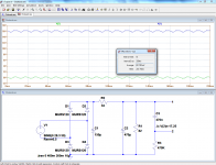
CRC filter. 150 uF, 33R, 470 uf. Dc out 16 V, load 82R , 0,19 A, Ac ripple 0,15 V.
CLC filter , everything the same, choke instead of 33R Ac ripple 0,01 V.
I am not going to throw away the choke.
And whatever others say: magnetic path isn't long. The choke is a tall stack of small E-I laminations.
And the choke is encased in iron sheet so stray magnetism should not be a problem.
And the PFC chokes from computer powersupplies can be used for DC filament supply because they are airgapped.
Without choke, the OP ripple of this circuit should be ~250mV. This looks way out compared to 150mV, but we have to remember that the typical tolerance on Elytics is something like -10/+50%, thus nothing abnormal there.Well Keit, I measured what I measured. The caps were very old and could be off value. Suggest me a nice testing circuit. L of the choke is around 1,4 H.
With a 1.4H choke added, the ripple is reduced to a bit more than 10mV.
In conclusion, everything looks correct.
Attachments

In conclusion, everything looks correct.
What are you playing at Elvee?
In your spice sim, you added a CR circuit on the end. The reactance of 470 nF at 100 Hz is 3388 ohms. As you put a 470 kohm resistor in series, that will give substantial extra attentuation.
You don't need SPICE to work out circuits this simple. It's a quick bit of mental arithmetic, see my working in my Post 30. As the output ripple is low compared to the DC, the current in the series resistor or choke is very nearly constant at 0.19 A. If the ripple on the first cap is small compared to the input peaks, and it turns out it is, then the input cap see a constant discharge of 0.19 A for nearly the period between half cycle, ie ~10 mS, and charged by the diodes for much less than 10 mS.
Therefore the pk-pk ripple on the first cap equals Tdischarge x Idischarge / capacitance; 0.01 x 0.19 / 150x10^-6 = 13 V. The mean DC input must be the output voltas plus the drop in the series resitor or choke, ie
16 + 0.19 x 33 = 22 V. So the ripple is not all that low compared to the DC value, so the diode conduction will be a little long, approx 3mS. But we are in the ball park. By simple proportion, the input cap ripple will be close to 10 volts.
This input capacitor ripple will be attenuated quite closely by the ratio of the reactance of the 470 uF cap to the imepdance of the series resistor or choke, as the reactance of the 470 uF cap is much less than the load. The cap reactance of is 1/(2piFC), ie 1 / (6.28 . 100 x 470x10^-6)
= 3.4 ohms. So the output ripple is approx 10 x 3.4/33 = 1 volt. That's nowhere near 0.15V, even if he measured RMS and not Pk-Pk as would normally be done. It's well above 0.44 volt, which is what you'll get with both caps at the top end of their +50% tolerance.
In conclusion, something's wrong with Steve's measurement.
That works out to an output ripple not with the ballpark of the measured value. In Steve tells us the measured ripple on the 150 uF cap, and how he measured it, we'll be in a better position to work out what's going on.
Last edited:
- Home
- Amplifiers
- Tubes / Valves
- Fluro Ballast as DIY choke?