This is a false problem: these are "reactors", not transformer's primaries, and they are designed to withstand the peak value of their normal operating current without saturating significantly. For a 18W part, the normal operating current would be 370mA rms, ie. 520mA^.As they are not designed to carry DC, they have no proper engineered airgap.
This means that the choke won't saturate until the instantaneous current reaches 520mA.
It could be the peak value of an AC waveform or a constant DC, it changes nothing. Note that they cannot withstand a permanent DC current of 520mA: the maximum rms current of 370mA is still the limit.
For that purpose, they do have some form of gapping, explicit or implicit.
Regarding leakage, I'm sure there horrendous examples around, but a well designed part can probably do better than a traditional EI construction, where the gap is situated at the junction of the E and the I and is allowed to leak towards the outside.
A false problem again: the typical self capacitance of such a ballast is in the tens of pF, perhaps 100pF for the worst. Compared to the tens of µF of typical supply filter caps this is negligible and other effects will dominate.Hello,
In addition to the concerns raised by the other gentlemen, you should consider this: a decent audio power supply choke will be constructed to minimise the self-capacitance between the windings, its flux leakage and susceptibility. This is significant, because the self-cap is in parallel with the inductance you want to use to reduce the power supply noise etc. This "cap" will do several bad things- it will form a parallel resonant circuit at several frequencies- quite a bit more complicated than the basic text book stuff.
It is also significantly less than the Cds capacitance of a high voltage MOSfet in a gyrator or capacitance multiplier.

This is a false problem: these are "reactors", not transformer's primaries, and they are designed to withstand the peak value of their normal operating current without saturating significantly. For a 18W part, the normal operating current would be 370mA rms, ie. 520mA^.
This means that the choke won't saturate until the instantaneous current reaches 520mA.
It could be the peak value of an AC waveform or a constant DC, it changes nothing. Note that they cannot withstand a permanent DC current of 520mA: the maximum rms current of 370mA is still the limit.
For that purpose, they do have some form of gapping, explicit or implicit.
Regarding leakage, I'm sure there horrendous examples around, but a well designed part can probably do better than a traditional EI construction, where the gap is situated at the junction of the E and the I and is allowed to leak towards the outside.
A false problem again: the typical self capacitance of such a ballast is in the tens of pF, perhaps 100pF for the worst. Compared to the tens of µF of typical supply filter caps this is negligible and other effects will dominate.
It is also significantly less than the Cds capacitance of a high voltage MOSfet in a gyrator or capacitance multiplier.
Well, gee, all those DC chokes I designed over the years using Hanna's Method must be strange devices then! Seriously, you need to look up books on choke design before writing such nonsense. Hanna's method provides a method of quickly choosing an optimum (minimum amount of iron to do the job) AND THE CORRECT AIRGAP, starting with the required L.I^2 value, where L is the inductance required to meet the ripple spec, and I is the DC - yes, DC - current the choke is required to carry.
It is well known that inductance falls sharply with the amount of DC current carried. The airgap reduces the fall off. The fact that inductance falls off sharply in iron cored chokes is the basis of magnetic amplifiers - I suggest you look these up too.
If you actually had tested power chokes, and/or looked the subject up, (LangfordSmith's The Radiotronics Handbook, or Henney's The Radio Engineering Hanbook will do), you would have found that layer-wound inductors can have considerable capacitance, well up in the tens or hundreds of nanofarad region. There are standard formulas used by design engineers to predict what it will be. Fluoro chokes are scramble wound to reduce cost. That makes the self capacitance somewhat unpredictable but generally larger than for an equivalent layer wound choke. Also the cheap non-optimal design of fluoro chokes does not make efficient use of the iron, and requires more turns to get the same inductance - increasing the self capcaitance still more.
Even so, the choke self capacitance will make no noticeable difference to the hum level. It will however pass through any higher frequency noise that arrives in the mains supply, including off-peak control tones that some power companies use. Chokes for power supply ripple suppression were made with layered windings usually separated by paper for this reason - to keep the self capacitance down.
Last edited:
I have myself a little experience designing power magnetic componentsWell, gee, all those DC chokes I designed over the years using Hanna's Method must be strange devices then! Seriously, you need to look up books on choke design before writing such nonsense. Hanna's method provides a method of quickly choosing an optimum (minimum amount of iron to do the job) AND THE CORRECT AIRGAP, starting with the required L.I^2 value, where L is the inductance required to meet the ripple spec, and I is the DC - yes, DC - current the choke is required to carry.
Hanna is one method for navigating among the many parameters and requirements of power inductors design, but it is just a method, and it is not the only one.
It may be fine in itself, but I personally don't like it very much which is why I have devised alternative methods, better suited to my workflow and methods.
I am not claiming they are superior, they do the job in a way that I find simpler and more agreeable, but that's probably a matter of personal taste.
The important thing is elsewhere: they yield an identical end result, but the Hanna method obscures some points in the process.
An inductor needs to have certain inductance and may not saturate within its range of working current. In principle, to know the induction in a core, you have to know the excitation ( "magnetic field", in A/m), the geometric and magnetic properties of the core and compute the resulting B.
In reality, a good analysis of the problem shows that very little input data is in fact necessary. For a core having an effective area Ae and a maximum induction B^, you just need to know the target inductance and the peak current to be able to compute the required number of turns. Will it be possible to wind all the turns required, how large will the gap need to be are not yet known at this stage, but the important thing to draw from that is that the induction (B) is proportional to the current. This remains true for AC, DC, or a mix of both. There is no difference in principle between the coil of a resonating convertor (pure AC) and a mains frequency smoothing choke (almost pure DC).
There are of course practical adaptations for each situation, but the requirement to stay out of saturation doesn't change, it is linked to the instantaneous current through the coil
More generally, the permeability and inductance fall sharply when the instantaneous current pushes the induction into saturationIt is well known that inductance falls sharply with the amount of DC current carried. The airgap reduces the fall off. The fact that inductance falls off sharply in iron cored chokes is the basis of magnetic amplifiers - I suggest you look these up too.
I am not talking about generalities here, the range of values I mentioned come from actual measurements on actual ballasts. I only tested a small number, and there are certainly wide variations between makers, but it gives an idea of what to expectIf you actually had tested power chokes, and/or looked the subject up, (LangfordSmith's The Radiotronics Handbook, or Henney's The Radio Engineering Hanbook will do), you would have found that layer-wound inductors can have considerable capacitance, well up in the tens or hundreds of nanofarad region. There are standard formulas used by design engineers to predict what it will be. Fluoro chokes are scramble wound to reduce cost. That makes the self capacitance somewhat unpredictable but generally larger than for an equivalent layer wound choke. Also the cheap non-optimal design of fluoro chokes does not make efficient use of the iron, and requires more turns to get the same inductance - increasing the self capcaitance still more.
We all agree on one thing: a ballast will never be able to outclass an inductor carefully and specifically designed for filtering, but it doesn't mean they are completely worthless for this task. They are cheap, and bring significant improvements compared to resistors, or nothing at all.
Elvee, you still haven't told us how you tested those ballasts. In-circuit in an amplifier, or on an instrument of some kind that measures inductance while pasing the rated or desired amount of direct current? Or what?
Untill you do, none of your statements about ballasts mean anything, for the reasons I explained.
And if you are as an experienced choke designer as you claim, you would be well aware that a typical transformer/choke iron has a very curvy B-H curve - it doesn't suddenly go into saturation at a certain flux level, like some ferrites, it gradually eases into it. How far a design engineer wishes to push an iron core is something of an arbitary decision - it depends on how much loss he's prepared to tolerate and other factors.
Last edited:
Lots of people talkin', few of them know, Soul of a choke was created below.
And then I just tested it. (33 = DCR of ballast choke)
CRC filter. 150 uF, 33R, 470 uf. Dc out 16 V, load 82R , 0,19 A, Ac ripple 0,15 V.
CLC filter , everything the same, choke instead of 33R Ac ripple 0,01 V.
I am not going to throw away the choke.
And whatever others say: magnetic path isn't long. The choke is a tall stack of small E-I laminations.
And the choke is encased in iron sheet so stray magnetism should not be a problem.
And the PFC chokes from computer powersupplies can be used for DC filament supply because they are airgapped.
The method is not actually relevant to the discussion since we are talking about theoretical issues, but I don't mind showing it anyway.Elvee, you still haven't told us how you tested those ballasts. In-circuit in an amplifier, or on an instrument of some kind that measures inductance while pasing the rated or desired amount of direct current? Or what?
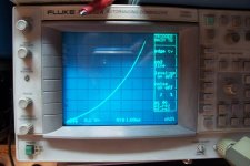
I use a special curve tracer, applying a calibrated voltage step (100V f.ex) to the DUT, and I measure the resulting current.
Thus, on the X-axis I read the V*s seen by the core (100V*ms/div in this example) and on the Y axis the current (100mA/div).
An ideal choke would display a straight line, with a slope inversely proportional to the inductance value.
A real inductor has various curvatures, due to saturation, RI drops, etc.
The curve gives a lot of information about the type of saturation (very gentle in this case), the different values of inductance under a power regime, amplitude, incremental, etc by looking at the local slopes, the intercepts, etc.
I extract the parallel capacitance from the self-resonance frequency
Attachments
Lots of people talkin', few of them know, Soul of a choke was created below.
And then I just tested it. (33 = DCR of ballast choke)
CRC filter. 150 uF, 33R, 470 uf. Dc out 16 V, load 82R , 0,19 A, Ac ripple 0,15 V.
CLC filter , everything the same, choke instead of 33R Ac ripple 0,01 V.
I am not going to throw away the choke.
And whatever others say: magnetic path isn't long. The choke is a tall stack of small E-I laminations.
And the choke is encased in iron sheet so stray magnetism should not be a problem.
And the PFC chokes from computer powersupplies can be used for DC filament supply because they are airgapped.
Exactly, the proof of the pudding is in the eating - and there are those who have partaken and those who haven't.
Shoog
Keit, I think if you took the time to test a part before bagging it then this post would better off. They are relatively low inductance compared to 10-20H behemoths, but that doesn't make them a bad choke.
They test fine as an inductance at 100Hz at relatively high levels of DC current, so to me they are a winner.
Agree that testing rules

FWIW I wind transformers commercially, and visiting my supplier I saw some E laminations on display which caught my attention, the E center leg was shorter.
When asked, he replied: "oh ... those? .... they are for old style Fluo ballasts ... nobody wants them any more".
So at least these had built-in gaps, like it or not.
I always wondered about getting some and testing some Single Ended transformers.
So if that built in gap is universal , that would explain the better than expected results.
Also the cheap non-optimal design of fluoro chokes does not make efficient use of the iron, and requires more turns to get the same inductance - increasing the self capcaitance still more.
This is a poor oversight Keit. Squillions of such chokes are not made to be 'non-optimal' - and I would suggest that the modern flouro choke is extremely optimal for the whole gamut of engineering requirements at play.
The flouro choke has to retain inductance at quite high current peaks, so that circuit breakers and fuses don't trip, and the starter bulbs don't fail in droves, as the flouro tubes age. This is a major operational issue. I wouldn't be surprised if the core gap was non-uniform in some, but that's probably a bit too expensive.
The welded seam technique previously highlighted as a poor technique is to my mind an excellent method. Some seem fixated that the weld seem is somehow modifying the magnetic path to the detriment of performance.
The choke in many power supply applications is to primarily lower the 2nd mains harmonic - as illustrated by those who happily parallel a 'huge' capacitor across the choke in order to resonate at the 2nd harmonic, and hence push the management of higher order harmonics and other rectifier hash on to the shunt capacitors in the supply.
Last edited:
Lots of people talkin', few of them know, Soul of a choke was created below.
And then I just tested it. (33 = DCR of ballast choke)
CRC filter. 150 uF, 33R, 470 uf. Dc out 16 V, load 82R , 0,19 A, Ac ripple 0,15 V.
CLC filter , everything the same, choke instead of 33R Ac ripple 0,01 V.
Something wrong with your data somewhere.
Taking the ripple frequency as 100 Hz (10 mS between diode conductions), back-of-the-envelope calculation shows the ripple on the first capcitor is approx 13 V Pk-Pk (V=It/C); The reactance of the second cap is 3.4 ohm ( 1/(2pi.f.C) ), low enough that the 82 ohm load has negligible influence. Therefore attenuation of the ripple is well approximated by the 2nd cap reactance divided by the series R - this leads to ripple amplitude across the load equal to 1.3 volt pk to pk (0.45 volt RMS).
You said you measured 0.15 V.
Your stated ripple (0.15V) with the choke is consistent with a choke inductance of only 0.46 henry, well below what a fluoro choke will display on AC, (and tiny compared to chokes intended for use in vacuum tube equipment power supplies, typically several henries).
While your data on the face of it supports the choke much improved compared to the 33 ohm resistor, there is something very wrong with your test somewhere, and until this is resolved, your results cannot be trusted.
Last edited:
Elvee's test he described in Post 26 is insteresting, but it's not testing the choke in a way that lets you determine just what it will do when carrying continuous DC.
Sorry chaps, you haven't shown me up yet.
My points I made earlier that:-
a) A flouro choke may well perform better than expected by the chaps who posted in the other (linked) thread who noted that they aren't intended for DC;
b) They most likely won't perform as well as a choke designed for power supply service
c) They don't look the part in tube equipment
d) With the large microfarad capactors available now, you don't need a choke in tube equipment unless its for restorative or cosmetic reasons
is not yet proven wrong.
While I haven't tested flouro ballasts as power supply chokes, I have plenty of experience with Ferguson's PL-series power transformers made on ballast tooling. They certainly put out plenty of stray field, and were notorious for doing so. So it is reasonable to expect fluoro ballasts to do the same.
Last edited:
You seem to have a mental block regarding DC and inductors.Elvee's test he described in Post 26 is insteresting, but it's not testing the choke in a way that lets you determine just what it will do when carrying continuous DC.
DC is nothing special for an inductor; problem with DC voltage is that it can lead to unpredictably high currents after a sufficient length of time, but when the current is imposed, no such thing happens, because the current governs directly the magnetic condition of the core, and in this case, only the instantaneous value is relevant (OK, hysteresis and eddy currents also intervene, but they are only second order effects).
From the graph, I can easily know the behavior of the inductor at any DC current, for example, just in the middle of the screen, the current is 350mA, and the local slope is 600mA/500V.ms.
The local value of inductance is simply the reciprocal of that slope: 500/600=833mH.
I have the impression that whatever is presented will have the same result....Sorry chaps, you haven't shown me up yet.
Attachments

...<snip>
If you actually had tested power chokes, and/or looked the subject up, (LangfordSmith's The Radiotronics Handbook, or Henney's The Radio Engineering Hanbook will do), you would have found that layer-wound inductors can have considerable capacitance, well up in the tens or hundreds of nanofarad region. There are standard formulas used by design engineers to predict what it will be. Fluoro chokes are scramble wound to reduce cost. That makes the self capacitance somewhat unpredictable but generally larger than for an equivalent layer wound choke. Also the cheap non-optimal design of fluoro chokes does not make efficient use of the iron, and requires more turns to get the same inductance - increasing the self capcaitance still more.
Even so, the choke self capacitance will make no noticeable difference to the hum level. It will however pass through any higher frequency noise that arrives in the mains supply, including off-peak control tones that some power companies use. Chokes for power supply ripple suppression were made with layered windings usually separated by paper for this reason - to keep the self capacitance down.
The question of leakage capacitance in a choke is a small problem, easily overcome using modern Suppression components.
For instance, if we find a choke with around 100nF of leakage capacitance (ie mod Z of about 1ohm at 1MHz), we can easily eliminate the risk of high frequency breakthrough by adding a tiny multi-turn ferrite bead. For instance the Laird 28C0236-0BW-10 arrives in packets of ten for a cost of -5.5dB(beer) Where 0dB = price of 568ml (1.0 pint) beer in my locality.
The 28C0236-0BW-10 has an impedance of >300 ohms at 10MHz, and >800ohms at 100MHz. Connect the bead in series with the supply choke, and add a stacked-construction capacitor to make a low-cost - but high performance HF filter that will surpass the insertion loss of any normal power supply choke.
28C0236-0BW-10 - LAIRD TECHNOLOGIES - FILTER, 6X10-15MM, 100MHZ, 835R | Farnell UK
If you need even more insertion loss, try the Wurth Elektronik 742 750 43 (~500 ohm @ 10MHz).
The big deal about using these old lighting chokes is that we often obtain them for nothing, or maybe 0dB(beer) at most. There is a pleasure in itself of creating something out of materials that would otherwise be thrown away!
The question of leakage capacitance in a choke is a small problem, easily overcome using modern Suppression components.
For instance, if we find a choke with around 100nF of leakage capacitance (ie mod Z of about 1ohm at 1MHz), we can easily eliminate the risk of high frequency breakthrough by adding a tiny multi-turn ferrite bead. For instance the Laird 28C0236-0BW-10 arrives in packets of ten for a cost of -5.5dB(beer) Where 0dB = price of 568ml (1.0 pint) beer in my locality.
The 28C0236-0BW-10 has an impedance of >300 ohms at 10MHz, and >800ohms at 100MHz. Connect the bead in series with the supply choke, and add a stacked-construction capacitor to make a low-cost - but high performance HF filter that will surpass the insertion loss of any normal power supply choke.
You can't be serious. There isn't any worry about 10 MHz - it will get attenuated by transformer leakage inductance (both power- and output-), and you can't hear it anyway. What can be a problem is mains-borne transients within the audio band, and power company control tones, which are also within the audio band. 100 nF has a reactance of 318 ohms at 5 kHz. Together with the HT rail electrolytic, that's sufficient to reduce power line transients and control tones to millivolts - that can be sufficient to get into signals circuits and be audible during quiet pasages in music.
When power companies started using control tones in the 1960's, there were a lot of complaints about audible control tones in tube-based hi-fi equipment and stereograms. In Australia, the then editor of "Electronics Australia" made a big thing about it.
But yes - the cure WAS and IS simple and cheap - a judiciously positioned resistor in the HT line.
Oh yeah, so everyone who has tried out the effect of reducing/removing reverse-recovery pulses in their rectifiers (bandwidth 10-100MHz+) is just imagining things. And of course, there is no danger of HF noise sources having any AM-modulation either (easily demodulated in preamps or solid-state "assistance" circuits). These HF sources can easily carry in audio spectrum and cause unpleasant effects.
Anyway, it was you that raised leakage capacitance as another bogus reason not to use Flourescent lamp chokes, and now you're saying it is not important.
I need not comment further about who is "serious".
Anyway, it was you that raised leakage capacitance as another bogus reason not to use Flourescent lamp chokes, and now you're saying it is not important.
I need not comment further about who is "serious".
Elvee, out of curiosity only (as it plays no part in the main thrust of this thread) I thought it worthwhile to go through the difference in measured inductance between your V=Ldi/dt method, and the method I use.
Your method measures inductance along the initial BH curve excitation locus when starting from zero BH. You can simply and safely push a choke deep in to saturation and see the inductance change in one visual sweep. To my mind, this technique is identical to a DCM flyback type operation.
The technique I use measures the incremental inductance around a small BH loop when a large standing DC current is passed. The measurement technique is then pretty close to how the choke is used in a smoothing application. It doesn't exercise the BH curve as in a choke input filter type application, where the BH loop traversed is much larger, and it takes many single point measurements to build up a picture of inductance variation, and any high DC current measurements have to be done cautiously so as not to over-heat the choke.
I never got around to setting up a test circuit as per how they did it in the olden days.
I just checked the self-resonant capacitance for the EC18/20 1.9H flouro choke I fortuitously have on the bench - about 150pF (ie. 10kHz SRF).
You seem to have a mental block regarding DC and inductors... the current governs directly the magnetic condition of the core, and in this case, only the instantaneous value is relevant
This is absolutely true. It took me years of working with all sorts of magnetic components before I got it. If some inductor saturates at, say, 500mA, it doesn't matter for practical purposes how the current of 500mA was achieved, whether it is the peak of an AC current waveform, a steady DC current, or whatever.
Concerns about build quality and flux leakage of the fluoro ballasts may well be valid, but concerns about saturation most likely aren't. I would go ahead and use them, it is in the DIY audio spirit 😎
Oh yeah, so everyone who has tried out the effect of reducing/removing reverse-recovery pulses in their rectifiers (bandwidth 10-100MHz+) is just imagining things. And of course, there is no danger of HF noise sources having any AM-modulation either (easily demodulated in preamps or solid-state "assistance" circuits). These HF sources can easily carry in audio spectrum and cause unpleasant effects.
Anyway, it was you that raised leakage capacitance as another bogus reason not to use Flourescent lamp chokes, and now you're saying it is not important.
I need not comment further about who is "serious".
It appears you have trouble reading.
It wasn't me that raised the issue of choke self capacitance, it was Glens in Post 15. Elvee then claimed this was a non-problem in his Post 21 - he said the capacitance was "tens of pF". Thats' wrong, its typically MUCH greater, so I said so in my Post 22, in which I explained that the choke self capacitance could let through noise and power company control tones. I would have thought it obvious that such noise and control tones would be at audio frequencies.
I never made any claim or statement about megahertz frequencies being a problem. You started that nonsense in your Post 33.
Your comment about HF problems in solid state equipment is not relavent - this forum and my comments are about tube circuits. It's not unknown, but you have to be very very unlucky to strike HF cross mod issues in tube preamps, where signals are well with the grid base, typically several volts. Solid state preamps are another matter - the working impedances are not dissimilar but transistor inputs are inherently non-linear over small fractional volt ranges.
The charge recovery effects in power diodes is not 10's of megahertz stuff, its way lower. Any charge recovery that occurs within megahertz cycle times is not going to do much as each diode only gets to turn off at the 50 Hz rate.
Please read the posts of others more carefully before trying to bag them.
Last edited:
Keit you seem to be hunting for arguments. You simply don't see that these chokes work adequately as power supply chokes, all but less well than commercial PS chokes designed for this application. All of the points you have made are a distraction from the simple fact that placing one of these Fluro chokes in a valve power supply will improve filtering and they are freely available to the person who asked the question.
I think it has been well established from an anecdotal and technical standpoint that they do work as DC chokes within certain limits.
I have to ask - what’s your beef with that ???
Shoog
I think it has been well established from an anecdotal and technical standpoint that they do work as DC chokes within certain limits.
I have to ask - what’s your beef with that ???
Shoog
Last edited:
Keit you seem to be hunting for arguments. You simply don't see that these chokes work adequately as power supply chokes, all but less well than commercial PS chokes designed for this application. All of the points you have made are a distraction from the simple fact that placing one of these Fluro chokes in a valve power supply will improve filtering and they are freely available to the person who asked the question.
I have to ask - whats your beef with that ???
Shoog
None, except that a simple resistor may in practice do as well, especially now that large capacity electrolytics are available - they were not pre-transistor era. Please read my post Post 31, especially my point (a) in that post.
What I do have a beef with is folk who choose to misread what I said, and set out to write a load of nonsense with the apparent aim of discrediting me.
What I do have a beef with is folk who mislead or confuse newbies when they should know better.
The original poster asked about using fluoro ballasts as power supply chokes in tube based equipment. Trobbins in his Post 4 included a link to another thread that supports his reasonable contention that as they are not intened to carry DC, performance is likey to be poor. I then pointed out that as fluoro ballasts do in fact have a fortuitous gap, that while they won't be as good as purpose designed power chokes, they never the less should perform better than expected.
Others then chose to misrepresent what I said.
Last edited:
- Home
- Amplifiers
- Tubes / Valves
- Fluro Ballast as DIY choke?