My first choice would be 6mA = 200mW = 100/120 Ohm? I am thinking that 1mA is a bit to low. And: you must start using a Tian probe 🙂
6mA in the input transistor ?
how can I learn how to use the Tian probe ?
6mA in the input transistor ?
how can I learn how to use the Tian probe ?
No, the new emitter follower 🙂
See the file "C:\Program Files (x86)\LTC\LTspiceIV\examples\Educational\LoopGain2.asc"
Member
Joined 2009
Paid Member
Why would you need so much current through the emitter follower ? - seems rather high. A lower current allows higher value resistors and higher value resistors which means more local feedback for the follower and lower distortion ?
Why would you need so much current through the emitter follower ? - seems rather high. A lower current allows higher value resistors and higher value resistors which means more local feedback for the follower and lower distortion ?
It was my idea to use 6mA as the starting point, not the finishing point. That is why I said that using (or learning to use) a Tian probe would be of value. In general I think that it is more dangerous to under bias a circuit (so 6mA may be a good starting point and then work/test downward).
Edit: try here: Solutions - LTspice IV: Stability of Op Amp Circuits
Bear in mind that it's not quite as simple as it looks - the extra device is not just an emitter follower in the 'beta enhanced VAS' topology as D. Self calls it. The emitter follower is also used to directly bootstrap the collector load of the input transistor. Therefore, there is an interplay between the resistor values.
Must study this very carefully 🙂
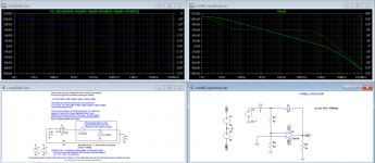
To simulate the open loop gain I resort to the simple approach of inserting an a.c. voltage source into the feedback loop and then plotting the ratio of the voltage on one side of it with respect to the other side as a function of frequency - you are effectively injecting a signal into the feedback loop and measuring the gain and phase. Somewhere around there there's a good link to see how it's done but I can't remember where it is - there may actually be an example file in the LTSpice examples folder. Edit: try here: Solutions - LTspice IV: Stability of Op Amp Circuits
This method is very simple and I also use it, but is not very accurate, the best method is the TIAN probe but very complex. I also like the Bob Cordell method, it is very simple and intuitive, and give results similar to the Tian probe as long the open loop impedance of the amplifier is relatively low (that is the case of almost every audio power amplifier).
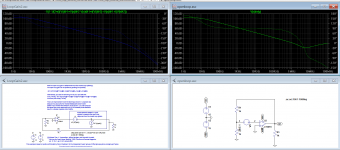
this images represent the 3 methods with the same circuit.
the first image is the tian method vs the bob cordell method.
the second image is the tian method vs the method apresented in the video that Bigun posted. As one can see the difference is huge and can lead to not so good conclusions.
Attachments
Going back to my actual amp, I would now like to try an emitter follower inside the miller loop.
Simulation seems ok but I would really appreciate some input regarding the schematic modifications and choice of values.
In order to lower input transistor current to the initial values I increased R3 from 680 to 1k1.
Can I use 2SA970 for the follower ? and what about it's emitter resistor... is 680 ok ?
2sa970 is fine a bc546c will also work, and 680 ohms or 1k1 is also fine.
Member
Joined 2009
Paid Member
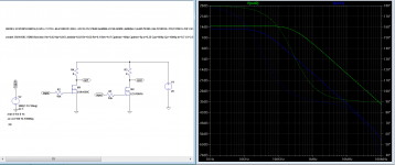
This is the third time I warn about the problems of the lateral models that is use in this thread, and will be the last one (I promise 🙂 dont want to be annoying )
So in the last attempt to explain what is the problem with the models post in #210, I made a simple circuit with the cordell model of the lateral mosfet and the model post in #210. this circuit use a 10k gate resistor to slow down the mosfet.
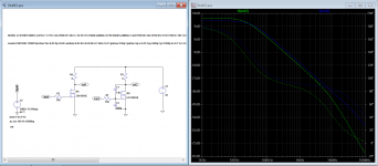
as one can see the first image shows that the #210 model is ten time faster that the cordell model, and that happens because the #210 model does not include the parasitic capacitors, in the second image is added Cgd and Cgs to the #210 and now the bandwidth is similar to the cordell model.
but the capacitors in cordell model varies in capacitance as the Vds varies, as a real mosfet will do.
Using the #210 model to simulate the stability of the amplifier is not advised and the result will be much different that the real amplifier . So... again my advice is to use the Cordell models.
So in the last attempt to explain what is the problem with the models post in #210, I made a simple circuit with the cordell model of the lateral mosfet and the model post in #210. this circuit use a 10k gate resistor to slow down the mosfet.
as one can see the first image shows that the #210 model is ten time faster that the cordell model, and that happens because the #210 model does not include the parasitic capacitors, in the second image is added Cgd and Cgs to the #210 and now the bandwidth is similar to the cordell model.
but the capacitors in cordell model varies in capacitance as the Vds varies, as a real mosfet will do.
Using the #210 model to simulate the stability of the amplifier is not advised and the result will be much different that the real amplifier . So... again my advice is to use the Cordell models.
Attachments
This is the third time I warn about the problems of the lateral models that is use in this thread, and will be the last one (I promise 🙂 dont want to be annoying )
So in the last attempt to explain what is the problem with the models post in #210, I made a simple circuit with the cordell model of the lateral mosfet and the model post in #210. this circuit use a 10k gate resistor to slow down the mosfet.
as one can see the first image shows that the #210 model is ten time faster that the cordell model, and that happens because the #210 model does not include the parasitic capacitors, in the second image is added Cgd and Cgs to the #210 and now the bandwidth is similar to the cordell model.
but the capacitors in cordell model varies in capacitance as the Vds varies, as a real mosfet will do.
Using the #210 model to simulate the stability of the amplifier is not advised and the result will be much different that the real amplifier . So... again my advice is to use the Cordell models.
Exicon datasheets indicate Ciss = 500p Coss = 300p and Crss = 10p for both items ECX10N20R and ECX10P20R
These values are quite different from the ones on the models 2SK1056C and 2SJ162C.
Please comment
The Exicons are really faster than The Hitachi's , but examining The Spice files, The capacitances are missing there, in simulation The Cordell models may be a better choice
Exicon datasheets indicate Ciss = 500p Coss = 300p and Crss = 10p for both items ECX10N20R and ECX10P20R
These values are quite different from the ones on the models 2SK1056C and 2SJ162C.
Please comment
Exicon. magnatec , semelab, renesas lateral mosfets are clones of the hitachi famous lateral mosfets, and are essential the same.
the parasitic capacitance's in a semiconductor are not static, they varies with voltage, for example the EXICON datasheet indicates a CISS of 500pf at Vgs of 0v but the renensas 2sj162 datasheet indicates 900pf at Vgs of 5v , but if you look at the graph on page 4 you will see that at Vgs=0v the 2sj160 have also 500pf of CISS, and if you look at page 3 of ECX10P20R , the CISS at Vgs=5v is 1100pf.
The semiconductor manufacturers can play a bit with datasheet numbers to make believe that their product are better than the ones offer by others.
The Crss in the Cordell model varies like a real mosfet do, and at Vds=30V will be 10pf at 100v will be 6.5pf and at 10v will be 20pf.
the Cgs is static at 600pf for the 2sk1056c.
The cordell model is not perfect, but will be more usable for simulation.
Last edited:
Thank you both.
I will use 2SK1056 and 2SJ160 from now on.
News: Just finished the beta enhancer mod and now I am trimming the offset.
Latter today I will be able to listen to it 🙂
I will use 2SK1056 and 2SJ160 from now on.
News: Just finished the beta enhancer mod and now I am trimming the offset.
Latter today I will be able to listen to it 🙂
I have been listening for a while now and can confirm that this mod was highly beneficial.
Now the amp has extended treble enabling me to hear the ever so important for large soundstage microdetail.
Completely lost is the harshness and the tight fast bass reappeared.
Now it sounds full detailed and fast.
I am really pleased with the results that prove my choice of building blocks was fine.
The initial Nobrainer concept (Thank you JG and FdW) added to the singleton input (Thank you Gareth), with carefully designed output stage with laterals (thank you Michael) is a total winner.
Must thank all involved (Sergio and all the others) for the patience and support.
I really learned a lot in the process and am particularly pleased to see my thread gathered so much attention.
Now is the time for The Circle.....
Just wondering..... Can The Circle be adapted in order to work as Current Feedback ?
PS: The Assemblage sounds really amazing.... Can not stop spinning my TT 🙂
Now you are an amp designer. Congratulation.
You are a most pleasant fellow so it was my pleasure to help.
Great that it sounds good too.
Maybe we should thank Douglas Self for that detail in the VAS.
You are a most pleasant fellow so it was my pleasure to help.
Great that it sounds good too.
Maybe we should thank Douglas Self for that detail in the VAS.
Nice to hear the you have great results...🙂
The circle is a current feedback design, you inject the FB direct in the current-path, you modulate the voltage, but as the input Jfet i referenced to GND, the modulated voltage is transferred into modulated current in the loop. Basically it is a tricky question because also so called CFA (VSSA and the likes) types live on modulated voltage. To me the CFA-VFA question is two sides of the same story, where true VFA's have FB injected through a device, and CFA have FB injected in the current path.
The circle is a current feedback design, you inject the FB direct in the current-path, you modulate the voltage, but as the input Jfet i referenced to GND, the modulated voltage is transferred into modulated current in the loop. Basically it is a tricky question because also so called CFA (VSSA and the likes) types live on modulated voltage. To me the CFA-VFA question is two sides of the same story, where true VFA's have FB injected through a device, and CFA have FB injected in the current path.
It seems to me that we need a low impedance input for NFB so it is sensible to current changes.
The mirror followed by the spreader can act as an I/V converter....
The mirror followed by the spreader can act as an I/V converter....
is quite a compliment.... Thank you again.Now you are an amp designer. Congratulation.
You are a most pleasant fellow so it was my pleasure to help.
Great that it sounds good too.
Maybe we should thank Douglas Self for that detail in the VAS.
Off course I must thank Mr. Self as I know the miller trick because I read his papers.
- Home
- Amplifiers
- Solid State
- Assemblage Power Amp