Also, in my hybrid thread, Damir has raised a good point on using a blue LED for VAS cascode offset. Blue LEDs are the most noisy ones - I know this, tested myself some time ago - I'm just not sure to what extent it will practically influence the overall noise profile.
The first one who builds one of these has to test it with the blue ones and, let say, a pair of red ones (those are definitely fine).
I have already reserved the place for a spare one on my PCB, just in case 🙂
The first one who builds one of these has to test it with the blue ones and, let say, a pair of red ones (those are definitely fine).
I have already reserved the place for a spare one on my PCB, just in case 🙂
LED Noise
From member Crister's work on diode noise:
http://www.diyaudio.com/forums/part...surements-leds-zener-diodes-7.html#post417008
EL202HD (red):
#1 @ 1mA: 0.31 0.32 0.31 0.31 0.32 uV
#1 @ 5mA: 0.26 0.26 0.27 0.27 0.27 uV
#1 @ 20mA: 0.39 0.36 0.37 0.36 0.37 uV
#2 @ 1mA: 0.39 0.37 0.38 0.38 0.35 uV (Vf = 1.82 V)
#2 @ 5mA: 0.32 0.30 0.30 0.30 0.31 uV (Vf = 1.89 V)
#2 @ 20mA: 0.41 0.40 0.41 0.41 0.46 uV (Vf = 2.09 V)
EL204UBD (blue):
#1 @ 1mA: 4.6 4.5 4.6 4.5 4.6 uV
#1 @ 5mA: 3.2 3.2 3.2 3.2 3.2 uV
#1 @ 20mA: 2.8 2.8 2.7 2.7 2.7 uV
#2 @ 1mA: 4.4 4.4 4.3 4.2 4.3 uV (Vf = 3.26 V)
#2 @ 5mA: 3.1 3.2 3.2 3.1 3.2 uV (Vf = 3.44 V)
#2 @ 20mA: 2.9 2.8 2.8 2.8 2.7 uV (Vf = 3.69 V)
So, assuming the noise in each of two red LEDs is uncorrelated, the resulting noise of 2 red LEDs in series at 5mA should be: SQRT [.26^2 x 26^2]
=0.367 uV RMS, considerably lower than one blue LED at 5mA producing 3.2uV RMS.
But, is that audible in the particular application?

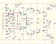
Running a blue LED is nothing compared to OPS distortion.
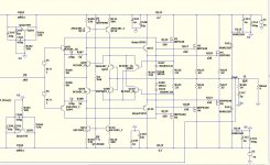
(Below 1) is a NON - switching Vfet/Lfet/BJT OPS.
It ....
A. Has the Hawksford error -correction (Q103 -106) , compensated
with (C1-2).
B. Has auto-bias and "Super A" (Below 2).
C. Bias is set both dynamically (Q107-110) ,
and by R111-112 .... the LED CCS's.
NO need for a Vbe circuit .... will work with VFET/LFET/BJT.
It essentially is class A -no device ever even comes close to shutoff.
THD is 10-20ppm high power 5-10ppm 1k/lower power.With NO NFB.
😎
OS
Attachments
Running a blue LED is nothing compared to OPS distortion.
(Below 1) is a NON - switching Vfet/Lfet/BJT OPS.
It ....
A. Has the Hawksford error -correction (Q103 -106) , compensated
with (C1-2).
B. Has auto-bias and "Super A" (Below 2).
C. Bias is set both dynamically (Q107-110) ,
and by R111-112 .... the LED CCS's.
NO need for a Vbe circuit .... will work with VFET/LFET/BJT.
It essentially is class A -no device ever even comes close to shutoff.
THD is 10-20ppm high power 5-10ppm 1k/lower power.With NO NFB.
😎
OS
Very clever dynamic biasing! Sensing not the temperature, but the current directly is great, and IS actually the way it should be 😎
That is Edmund Stuart's non-switching scheme.
Auto Bias part II
AB2ECV4
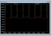
If you look at the transfer curve there is actually an extremely slight blip right at crossover, and it's size is proportional to the current through Q109 and Q110. So not perfect, but very nearly there.
Auto Bias part II
AB2ECV4
If you look at the transfer curve there is actually an extremely slight blip right at crossover, and it's size is proportional to the current through Q109 and Q110. So not perfect, but very nearly there.
That is Edmund Stuart's non-switching scheme.
Auto Bias part II
AB2ECV4
If you look at the transfer curve there is actually an extremely slight blip right at crossover, and it's size is proportional to the current through Q109 and Q110. So not perfect, but very nearly there.
And discussed here: http://www.diyaudio.com/forums/solid-state/202684-class-i-siblings.html
As it happened several time to me to get poor numbers while simulating slew rates after the output protective coil, this points is important for a fair comparison.
This is my method to set an amp.
- First, I remove any input filter and compensate my amp, looking BEFORE the output coil, for max flat bandwidth with no peak in the response curve at hf.
(I use 8 Ohms as a charge)
- I verify i have no overshoot with large square signals, not saturated.
- I apply a square wave signal at the input large enough to saturate the amp.
- I measure the speed of the signal at output, (before the coil), between 10% (bottom) and 90%(top) of the amplitude. This make 80% (normalised) of the amplitude to get the slew rate number.
- Now, I apply a little square wave (1mv or so) at the input, and set my input filter in order to have no overshoot. (always before the coil). The amp is tuned.
If you measure after the coil, you'll have never more than 300V/µs, due to the inductance, and, what we want to know, with slew rate, is the real speed of the electronic, of course.
Hoping it helps.
Last edited:
What I find interesting about your method is that you allow the small-signal square wave to have some overshoot, and just use the input filter to swamp it out.
Post
You're right, amps won't eat any square waves. Tortured with infinite fast transients any amp will be pushed beyond its limits.
In case of this amp I don't know yet what causes it to get 'berserk'. Saturation, lack of headroom of the bias circuit, missing Baker clamps? With vert. MOSFETs I got much higher slew rates. Maybe AB2 doesn't like BJT output devices anyhow. I have to figure that out.
Yes , the designer himself describes AB2 as "slewrate limited".
So , I'm not crazy ! OPS "choked" on my uber fast CFA's.
The standard EF3 OPS can take a .01uS risetime with ease.
Still , the IRF's (VFET's) and their 5V Vgs get along well with this
OPS.
Thanks for link ..... I actually came to the same conclusions 😎
(without the benefit of the link) ...
OS
Just for the fun, highly optimized DVSSA (1200V/µs, <4ppm H.D.) is here:
http://www.esperado.fr/vssa-diamond/dvssa.php
http://www.esperado.fr/vssa-diamond/dvssa.php
Just for the fun, highly optimized DVSSA (1200V/µs, <4ppm H.D.) is here:
http://www.esperado.fr/vssa-diamond/dvssa.php
I'm using the diamond topology almost 25 years with Darlington outputs.
These is really clever solution to get read of some of the problem (instability) goes with the diamond.
Nice I like it a lot.
I would test (compare) it if there is a PC board for these with the req. diamond topology.😀
Greetings
Does the slew/PPM even matter if the OPS is not accurately reproducing
these attributes ?
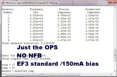
Ahhh , to simulate our typical OPS's (EF - 2/3) in isolation is quite sobering.
They really suck !! 😱
The "slewmaster" EF3 is the best of them , with .05 - .08% THD20.
A typical EF2 (a DX OPS 😛 ) is .2% or much worse !!
BUT .... why would we care about this? We could just swamp all this
badness out with lot's O' feedback.
(below 1) is a typical EF3 with IRFP VFETS. .18% with increasing
amounts as you "crank it up". An EF2 Vfet is at best a SUB amp , I
would not want a <1% THD OPS running my tweeters. 🙁
To try for PPM / high slew input stages and NOT at least attempt ... to
"purify" the power stage is a halfar$ed approach.
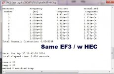
(Below 2) is the exact same OPS with the IRF's .... 🙂
NOW ... I see why Mr. Cordell did this , increased PSRR ,
actually decreasing THD with load and power.
I had the PGP amp (Lfet's) and Cordell's paper (Vfets) as inspiration.
I have tried all 3 "flavors" BJT/Vfet/Lfet - they all taste good !!
THD is reduced by >10:1 up to 20:1 with BJT's (they work best).
BJT's are the most linear (suitable for audio) of the 3.
Vfet's are NOT good audio devices (switches w/ high Vgs on).
(below 3) is the output ...
As advertised , the ratio of the sum of (R112/113) versus (R115/116)
forms the "perfect" cancellation signal to feed the HEC semi's (Q109/110).
"Rhec" is a 100R trimmer , which can fine tune this balance.
Just 20% off- balance can make .01% into .05% ... better than a typical
OPS , but (properly "tuned") is preferred.
-Advantages
1.- Far less OPS THD .... which translates into a spooky IPS that will
be @ 5 PPM 1-20k full power ! 😀 THD even drops from 10W to 100W.
PS-available negative feedback has an easier job with this OPS.
2.-Lower PSRR , parasitic rail feedback is cancelled.
3.- LOUSY non-linear VFETS behave more like BJT's .. (instead of switches).
PS - lower TIM/PIM .... 😎
-Disadvantages
1. You lose headroom , a voltage doubler/boosted rail is a given. You
lose 14V between rails (w/ Vfets).
2.- You also lose (some) slew , since the feed-forward has phase shift.
3.- more devices .... nothing comes without trying (harder). 😀
This is the most stable of all the "enhanced" OPS's I've tried.
It will "eat them square waves" nicely , does not affect UG/PM ,
and "plays" very nicely with the IPS's.
OS
these attributes ?
Ahhh , to simulate our typical OPS's (EF - 2/3) in isolation is quite sobering.
They really suck !! 😱
The "slewmaster" EF3 is the best of them , with .05 - .08% THD20.
A typical EF2 (a DX OPS 😛 ) is .2% or much worse !!
BUT .... why would we care about this? We could just swamp all this
badness out with lot's O' feedback.
(below 1) is a typical EF3 with IRFP VFETS. .18% with increasing
amounts as you "crank it up". An EF2 Vfet is at best a SUB amp , I
would not want a <1% THD OPS running my tweeters. 🙁
To try for PPM / high slew input stages and NOT at least attempt ... to
"purify" the power stage is a halfar$ed approach.
(Below 2) is the exact same OPS with the IRF's .... 🙂
NOW ... I see why Mr. Cordell did this , increased PSRR ,
actually decreasing THD with load and power.
I had the PGP amp (Lfet's) and Cordell's paper (Vfets) as inspiration.
I have tried all 3 "flavors" BJT/Vfet/Lfet - they all taste good !!
THD is reduced by >10:1 up to 20:1 with BJT's (they work best).
BJT's are the most linear (suitable for audio) of the 3.
Vfet's are NOT good audio devices (switches w/ high Vgs on).
(below 3) is the output ...
As advertised , the ratio of the sum of (R112/113) versus (R115/116)
forms the "perfect" cancellation signal to feed the HEC semi's (Q109/110).
"Rhec" is a 100R trimmer , which can fine tune this balance.
Just 20% off- balance can make .01% into .05% ... better than a typical
OPS , but (properly "tuned") is preferred.
-Advantages
1.- Far less OPS THD .... which translates into a spooky IPS that will
be @ 5 PPM 1-20k full power ! 😀 THD even drops from 10W to 100W.
PS-available negative feedback has an easier job with this OPS.
2.-Lower PSRR , parasitic rail feedback is cancelled.
3.- LOUSY non-linear VFETS behave more like BJT's .. (instead of switches).
PS - lower TIM/PIM .... 😎
-Disadvantages
1. You lose headroom , a voltage doubler/boosted rail is a given. You
lose 14V between rails (w/ Vfets).
2.- You also lose (some) slew , since the feed-forward has phase shift.
3.- more devices .... nothing comes without trying (harder). 😀
This is the most stable of all the "enhanced" OPS's I've tried.
It will "eat them square waves" nicely , does not affect UG/PM ,
and "plays" very nicely with the IPS's.
OS
Attachments
Last edited:
Just for the fun, highly optimized DVSSA (1200V/µs, <4ppm H.D.) is here:
http://www.esperado.fr/vssa-diamond/dvssa.php
It was to good to be true, so I simulate it using Cordell modes real CCS and bias spreader. My simulations were far from yours, SR and distortion. I like your use of OIC.
Could you load your .asc file, I would like to see why I've got so big difference.
Dmir
Hmm I have to try this HEC in my OPS and see if that would yield an overall improvement without giving up margins 🙂 Are the principles behind it explained somewhere? Maybe in Bob's book?
CordellAudio.com - A MOSFET Power Amplifier with Error Correction
and ...
Schematics
The ultimate "book" is the actual simulation of it.
Edit - here is the "original" ... http://www.linearaudio.nl/linearaudio.nl/images/pdf/hawksf%20ec.pdf
OS
and ...
Schematics
The ultimate "book" is the actual simulation of it.
Edit - here is the "original" ... http://www.linearaudio.nl/linearaudio.nl/images/pdf/hawksf%20ec.pdf
OS
Last edited:
I prefer Bjt 2-3 or more to output, example of Honey Badger is good to drive most of speakers,
(Dynaudio) Mass loaded speakers with many bassdrivers.
(Dynaudio) Mass loaded speakers with many bassdrivers.
3 pair BJT = 150W/8R , my favorite range. "Slewmonster" can have just
3 pair .. better thermal distribution.
OTOH , 3 pair IRFP-FET is a 400W beast. If only they were more "audio friendly".
HEC might facilitate this.
OS
3 pair .. better thermal distribution.
OTOH , 3 pair IRFP-FET is a 400W beast. If only they were more "audio friendly".
HEC might facilitate this.
OS
...My simulations were far from yours, SR and distortion...
Could you load your .asc file, I would like to see why...
Hi Damir
Every time I have checked another implausibly wonderful MOSFET simulation I have found useless FET models.
What were your distortion results?
If I am correct about the bad models then I expect at 20 kHz near full power your simulation would show 10 to 100 times more distortion.
I hope this saves you time if the ASC is posted.
Best wishes
David
Last edited:
- Home
- Amplifiers
- Solid State
- Slewmaster - CFA vs. VFA "Rumble"