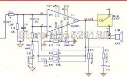
My test load is a 10 ohm resistor. There should be no distortion.It looks like transconductanc , the feedback is coming from the current going thru r7. Since it's a transconductance Amp the voltage out will look funny, (Distorted) but that dosen't matter, it's the curent (out) thru the speAker that should be the same as the input signal. Thus transconductance. I out= A Vin. Scope the voltag at r7.
It looks like transconductanc , the feedback is coming from the current going thru r7. Since it's a transconductance Amp the voltage out will look funny, (Distorted) but that dosen't matter, it's the curent (out) thru the speAker that should be the same as the input signal. Thus transconductance. I out= A Vin. Scope the voltag at r7.
Do you have a schematic?
Here is a link to the Chinese supplier
ºãÁ÷ÐÍTDA7294¹¦·ÅPCB¿Õ°å-ÌÔ±¦Íø
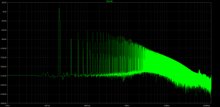
I scoped the shunt resistor. Horrible crossover distortion at 20 Hz. I am suspecting the diodes are in the feedback path and are causing the distortion.


My test load is a 10 ohm resistor. There should be no distortion.
Oh, your right ,should be a clean signal.
here is a couple of circuits I found on the web...
Your #3, but only 1 channel and no power supply.
I am thinking that the opamp may be inoperative. I will check the second of two that I purchased.
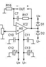
I am afraid that nothing beats this simplicity by Meriläinen:
This is the heart of all of the three schematics posted above.
There is a problem with this topology. It is sensitive the opamp input offset. I wrapped this around a power amp and it causes the output to stick to one of the power rails.
Schematic #3 above uses a servo to correct this problem. I need DC coupling and DC amplification so cannot tolerate the servo to 0 volts DC. Instead, adding an adjustment at the opamp input to re-center the input to 0 seems to be in order.
It is sensitive the opamp input offset. I wrapped this around a power amp and it causes the output to stick to one of the power rails.
this is only a part of the schematic from his (Meriläinen) site.
Of course a capacitor should be at the input.
From many of chipamps only TDA 2030/40/50 would do in case of stability.
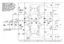
Here is an official schematic for the Optimus 1971. I have one in hand and will work on getting one channel modified. The schematic is hi-rez.

I think this 1995 Ian Hegglun's amp might be interesting as a lab instrument
with good DC stability eve, without input cap.
It could be adapted to have negative current feedback so as to behave as a transconductance amp.
Hello Forr
Can you post or link a higher resolution version?
Thanks for this, manually tracing was a pain so I didn't get to the power supply and protection circuits.Here is an official schematic for the Optimus 1971. I have one in hand and will work on getting one channel modified. The schematic is hi-rez.
View attachment 441001
Hello Forr
Can you post or link a higher resolution version?
Here it is. I hope it will not be considered as author's rights infringement.
I have a great admiration for all Ian Hegglun's works.
I never heard of someone having built this amp.
I hope to do it one day myself as it it seems very interesting for experimental purposes and it is quite simple.
Attachments

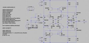
the performance is not outstanding
Noise and distortion performances should be largely sufficient for the purpose of a lab amp having low intrinsic DC offset and being able to be used as a good AC and DC transconductance amp with the adequate feedback.
Here it is. I hope it will not be considered as author's rights infringement.
I have a great admiration for all Ian Hegglun's works.
I never heard of someone having built this amp.
I hope to do it one day myself as it it seems very interesting for experimental purposes and it is quite simple.
Thanks Forr. I will save this.
Thanks for this, manually tracing was a pain so I didn't get to the power supply and protection circuits.
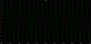
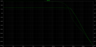
I received an Otimus 1971. Checking it out before the surgery. It puts out about 16V AC into 10 ohms before clipping. Noticeable 1V RMS output droop at 20 kHz. Nice low freq response, no droop at 2 Hz.
I will open it up and start preparing it for the switch to transconductance mode per your schematic.
Do you have any pictures of the inside after your mod?
Did you adjust RV1 & 2 (your R15/16) as in the article?the performance is not outstanding🙄
- Home
- Amplifiers
- Solid State
- Current drive for Loudspeakers