woofertester, any update on your project?
Hello
I have purchased several current drive PCBs from eBay. One uses a TDA chip amp. Two of them use the LM3886 chip amp.
All of them are noisy, oscillate, etc.
I am going to try to use the idea that jerluwoo has posted. I may use a VSSA module that I purchased from Lazy Cat.
I have approached a couple of designers to design one from scratch. That will cost many thousands of dollars.
I see one basic problem. Fast signal changes require fast curent changes, which in large drivers ( big inductors ) require large voltages. In amps, large currents are easy, parallel output devices. Large voltages, not so easy, or safe. With out the numbers I can't say what voltages are necessary, but are 500v amps practical?
I see one basic problem. Fast signal changes require fast curent changes, which in large drivers ( big inductors ) require large voltages. In amps, large currents are easy, parallel output devices. Large voltages, not so easy, or safe. With out the numbers I can't say what voltages are necessary, but are 500v amps practical?
50W/8R is plenty for many applications. Maximum voltage is 24VAC and current is 2A RMS. This is what I am looking to develop.
Subwoofers are another animal entirely. Large voltages and large currents may be required.
For a given frequency response you'll need a certain amount of voltage and current and it does NOT change with drive impedance -- no matter how complex it may be -- because any change of voltage or current in the driver would yield a different frequency response. In other words, if you measure a driver's voltage and current it stays the same when you change drive impedance but force the frequency response to be the same (by EQing).I see one basic problem. Fast signal changes require fast curent changes, which in large drivers ( big inductors ) require large voltages. In amps, large currents are easy, parallel output devices. Large voltages, not so easy, or safe. With out the numbers I can't say what voltages are necessary, but are 500v amps practical?
Drive impedance, though, has an effect on distortion, thermal compression, large signal behaviour etc, even with the same frequency response, that's why it matters in the first place and what we want to optimize for.
Last edited:
@woofertester
No need for *pure* current drive up to 20kHz im my experience. If you approach the Z of the driver at 20kHz (some 10s of ohms) it's good enough and not hard to design with any chipamp -- at least for a given and fixed (undetachable, fixed cabling etc) driver or speaker.
EDIT: Did you happen to measure/test the PCBs without a proper load? That might explain why you found them noisy and oscillating....
Last edited:
@woofertester
No need for *pure* current drive up to 20kHz im my experience. If you approach the Z of the driver at 20kHz (some 10s of ohms) it's good enough and not hard to design with any chipamp -- at least for a given and fixed (undetachable, fixed cabling etc) driver or speaker.
EDIT: Did you happen to measure/test the PCBs without a proper load? That might explain why you found them noisy and oscillating....
My "need" for current drive is to eliminate back emf which eliminates current distortion.. This allows me to capture current with speaker behaviors; excursion, position, velocity, etc.
Most of my work is below 100 Hz, at Fs where voltage and current are in phase.
I think I found the noise problem. It is digital noise from the signal generator. The gain of this PCB into 10 ohms is 300 which is much too high. The transconductance of the amp is 30 A/V. A value of 2 would be much better
This looks elegant. Is the output inverting with respect to the input?
Output is not inverting.
Output is not inverting.
Can you post the original schematic? And model number of the amplifier?
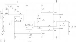
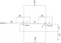
Model no. 12-1971A These pop up on ebay all the time. 2X50Watts@4ohm. Attached is the schematic that I manually traced, no schematic that I have found available. There is a bill of materials for this model number on radio shacks archive ftp, But I found none of the semiconductors are the same as in my amp. The driver and output semi's aren't correct in the schematic, using the closest I could find to sim, have to open it back up to see what the originals are. I changed only the opamp section by removing/changing a couple of resistors and adding .33 5watt resistors between spk out ground terminals and pc board and 4 jumper wires.
(edit) woops.. you can ignore the load after the zobel
(edit edit) http://www.ebay.com/itm/Optimus-Hig...7415390?pt=Car_Amplifiers&hash=item23412e66de
(edit) woops.. you can ignore the load after the zobel
(edit edit) http://www.ebay.com/itm/Optimus-Hig...7415390?pt=Car_Amplifiers&hash=item23412e66de
Attachments
Last edited:
Model no. 12-1971A These pop up on ebay all the time. 2X50Watts@4ohm. Attached is the schematic that I manually traced, no schematic that I have found available. There is a bill of materials for this model number on radio shacks archive ftp, But I found none of the semiconductors are the same as in my amp. The driver and output semi's aren't correct in the schematic, using the closest I could find to sim, have to open it back up to see what the originals are. I changed only the opamp section by removing/changing a couple of resistors and adding .33 5watt resistors between spk out ground terminals and pc board and 4 jumper wires.
(edit) woops.. you can ignore the load after the zobel
(edit edit) Optimus High Power 100 Watt Stereo Amplifier w MOSFET Power Supply 12 1971 | eBay
Thank you very much for posting the original schematic.
I definitely do not understand the change nor the original.
In the original version, the audio input is applied to the + terminal of the opamp and the opamp drives LTPs at where the amplifier feedback is connected.
The modified version has the audio input on the - terminal of the opamp and the current shunt feedback is applied to the + terminal of the opamp.
I am definitely not following either original or the modified amp.
A simplified way to look at it. The concept works identical to the My_Ref Fremen Edition amp that is discussed in the chipamp forum. This can be optimized quite a bit more but I didn't want to make any alterations to the pc board.
Attachments
Last edited:
A simplified way to look at it. The concept works identical to the My_Ref Fremen Edition amp that is discussed in the chipamp forum. This can be optimized quite a bit more but I didn't want to make any alterations to the pc board.
Thank you for the explanation. Is the original, un-modified amp inverting?
Thank you for the explanation. Is the original, un-modified amp inverting?
Yes it was, which I thought was odd.
Yes it was, which I thought was odd.
Thanks. That threw me off initially. Now it makes sense.
Do you use this amp in your car or did you re-purpose it for use in your home?
car amp makers use left - inverting
......................... right - noninverting
so you can y-cord one channel into L + R
AND !
L + R comes out a balanced (bridged) output
......................... right - noninverting
so you can y-cord one channel into L + R
AND !
L + R comes out a balanced (bridged) output
Using it as my PC sound at home with a 300watt ATX supply. It drives an old pair of magnavox 2-ways, sounds nice, clean and detailed. Would never suspect the outputs are biased right at the class B/AB threshold, voltage drop across the .22 emitter resistors only a couple millivolts. Now if I could find my other 1k 10-turn I would mod the bias circuit, I know its around here somewhere.
hitsware, this is a non-bridgeable model, probably the base model of models for Radio Shacks car amps from this period. The outputs may survive a brief stint at 2 ohms but the drivers would surely smoke, they are the oversized to92 looking package.
(edit) pulled the bottom cover to get numbers on drivers/outputs- driver 2sc2235/2sa965 outputs Mospec BD907/908
Last edited:
For a given frequency response you'll need a certain amount of voltage and current and it does NOT change with drive impedance -- no matter how complex it may be -- because any change of voltage or current in the driver would yield a different frequency response. In other words, if you measure a driver's voltage and current it stays the same when you change drive impedance but force the frequency response to be the same (by EQing).
Drive impedance, though, has an effect on distortion, thermal compression, large signal behaviour etc, even with the same frequency response, that's why it matters in the first place and what we want to optimize for.
Don't think so: V=L di/dt. So for large inductors, and large and fast current changes the voltages are high. It's the same as driving capacitive loads with voltage drive, you will need a high current capability. ( look into collapsing fields in a coil, like getting kVolts from a 12 volt car battery to drive your spark plugs)
The unknown is the damping R caused by the acoustic coupling, which should reduce this voltage. Have no idea how large this will be.
Don't think so: V=L di/dt. So for large inductors, and large and fast current changes the voltages are high. It's the same as driving capacitive loads with voltage drive, you will need a high current capability. ( look into collapsing fields in a coil, like getting kVolts from a 12 volt car battery to drive your spark plugs)
Good point. Realistically, the largest currents are at low frequency where d/dt is small. Where d/dt is large, at high frequencies, currents are small.
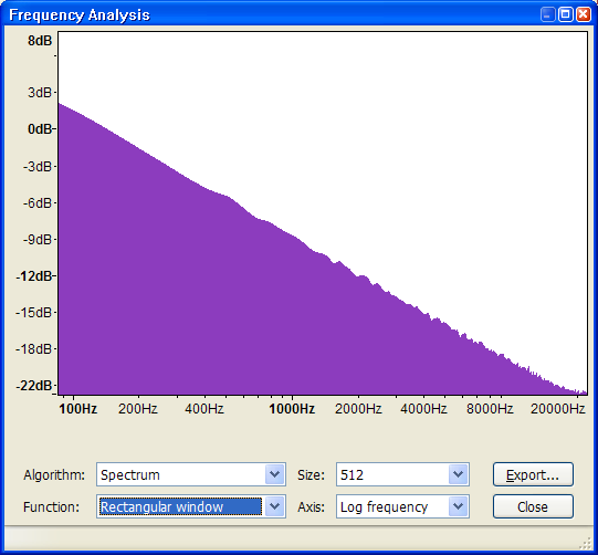
If you take an FFT of an entire song, you get the power envelope. This envelope for most music looks like pink noise:
Hello
I have purchased several current drive PCBs from eBay. One uses a TDA chip amp. Two of them use the LM3886 chip amp.
All of them are noisy, oscillate, etc.
I am going to try to use the idea that jerluwoo has posted. I may use a VSSA module that I purchased from Lazy Cat.
I have approached a couple of designers to design one from scratch. That will cost many thousands of dollars.
woofertester, try to power those ebay kits with well regulated external power supply, even the kit has rectifier and filtration capacitors on the board and only needs AC...I had luck with problematic current amp kits to tame them this way
- Home
- Amplifiers
- Solid State
- Current drive for Loudspeakers