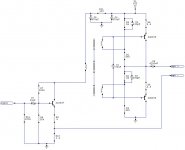
OK. I take it you have this built up with PSUs etc."Anyone got a link to the 'final' schematic?"
I believe this is rev C.
revcschem9-1-2006.pdf
Is this originally an EasyPCB file? That would make things easier.
Do the component numbers on the schematic match your eBay unit?
______________________
What's the maximum voltage that WTpro gives out?
______________________
Did you mean "square wave with any fidelity." ?Both of these boards had ringing/oscillation with a resistive dummy load. They would not pass a sine wave with any fidelity.
Last edited:
.OK. I take it you have this built up with PSUs etc.
No I have not built one yet.
Is this originally an EasyPCB file? That would make things easier.
I do not know.
Do the component numbers on the schematic match your eBay unit?
The eBay unit has not part numbers on the PCB. Only part values. Useless for debugging.
______________________
What's the maximum voltage that WTpro gives out?
About 1.5v rms.
______________________
Did you mean "square wave with any fidelity." ?
No I mean that a 17 Hz sine wave becomes garbage due to the oscillation.
If your TDA chip amp design is stable, that would be a good starting point for a chip amp current source.
Last edited:
You need to build a nx-Amp.
If the amp was super-high output impedance, I would in a heartbeat.
If the amp was super-high output impedance, I would in a heartbeat.
80 Ohms high enough ?
FIRST WATT F1
80 ohms is no where near enough. In addition the F1 is 5% THD at 9 watts. You would not be able to measure the linearity of the speaker with this amp.
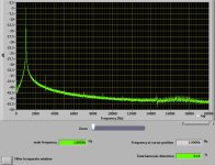
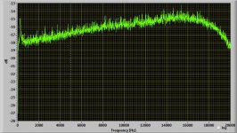
Just sharing my desktop amp since it's on topic here. Repurposed from a late 60's Sears under dash 8-track. A few small mods and this little amp became extremely enjoyable to listen to.
Measurements were taken with the speakers as load not a resistor. Easily spotted is the peak at 240Hz, the resonance of my speakers.
Measurements were taken with the speakers as load not a resistor. Easily spotted is the peak at 240Hz, the resonance of my speakers.
Attachments
Last edited:
These are very interesting. however, the voltage limit is much too low on these amplifiers. They are intended to develop massive current into almost a dead short.
I noticed that. What voltage swing do you need ?These are very interesting. however, the voltage limit is much too low on these amplifiers. They are intended to develop massive current into almost a dead short.
Perhaps one of those type amps with a good transformer ?
BTW - is motional feedback considered a form of current drive?
THx-RNMarsh
Yes
Woofer, I sent you a PM asking for your email address. I'd like to send you a draft proposal for a WTpro Transconductance Amp using ChipAmps.
I'm not sure if we can use a simple resistor in the earthy lead of the speaker to get Current Drive with WTpro. I think you said WTpro current measurement required a resistor to earth.
Can you post a sketch of how you connect your supadupa current source amp with WTpro?
I'm not sure if we can use a simple resistor in the earthy lead of the speaker to get Current Drive with WTpro. I think you said WTpro current measurement required a resistor to earth.
Can you post a sketch of how you connect your supadupa current source amp with WTpro?
The WTPro has a shunt to ground. If a chipamp is used in a grounded shunt configuration, the signal across the shunt can be buffered and brought out to replace the shunt used in the WTPro. The WTPro shunt is mounted outside and is removable.
If a Howland current pump is employed, there will be two shunts in the system which will wast a little bit of voltage swing but no big deal in the grand scheme.

If a Howland current pump is employed, there will be two shunts in the system which will wast a little bit of voltage swing but no big deal in the grand scheme.
Woofer, I sent you a PM asking for your email address. I'd like to send you a draft proposal for a WTpro Transconductance Amp using ChipAmps.
I'm not sure if we can use a simple resistor in the earthy lead of the speaker to get Current Drive with WTpro. I think you said WTpro current measurement required a resistor to earth.
Can you post a sketch of how you connect your supadupa current source amp with WTpro?
I replied to your email. Thanks for corresponding.
I noticed that. What voltage swing do you need ?
Perhaps one of those type amps with a good transformer ?
A "small" amp should be able to do 28V RMS and 2A RMS. The "big one" I had built does 48V RMS and 4A RMS.
The transformer is an interesting idea. I do not think it is a workable solution because of several reasons.
1. Hysteresis/distortion
2. phase problems
3. It blocks DC
A "small" amp should be able to do 28V RMS and 2A RMS. The "big one" I had built does 48V RMS and 4A RMS.
The transformer is an interesting idea. I do not think it is a workable solution because of several reasons.
1. Hysteresis/distortion
2. phase problems
3. It blocks DC
1) Very little distortion if transformer is carefully chosen.
2) See 1
3) Why do you need to pass DC ?
(Re can be measured at a lower current
(lest you burn the VC))
I really think you'd get better results from
professionally made test equipment, rather than
something hacked together with TDA whatever.
To avoid the sensing resistor being connected to ground, Merilainen suggests (in his book pp 190-191) to insert it between the power amp output and the load, the voltage across it being sensed by an op-amp (NE5534) in differential mode. The output of this op-amp is connected to the inverting input of the power amp and a Zobel RC is added across the load.
Last edited:
1) Very little distortion if transformer is carefully chosen.
2) See 1
3) Why do you need to pass DC ?
(Re can be measured at a lower current
(lest you burn the VC))
I really think you'd get better results from
professionally made test equipment, rather than
something hacked together with TDA whatever.
Nobody makes an off-the-shelf amp I need.
DC bias is useful to look at T/S parameters vs DC offset. It is a way to find voice coil offset. Also being able to plot excursion vs current at 1Hz is useful. There is a great AES article on using an accelerometer to find Qt at high excursion.
Creating a DIY amp of the kind I am envisioning will be useful for hobbyist loudspeaker enthusiasts. Most of my customers are loudspeaker DIYers.
Most useful products started out as a hacked prototype. The first WT was a hack on my bench to replace a pile of test equipment and save me tons of time.
To avoid the sensing resistor being connected to ground, Merilainen suggests (in his book pp 190-191) to insert it between the power amp output and the load, the voltage across it being sensed by an op-amp (NE5534) in differential mode. The output of this op-amp is connected to the inverting input of the power amp and a Zobel RC is added across the load.
That is on my list of things to try. Do you think it practical to develop a box to implement the idea you describe? You could use the box with any generic amp to make it force current.
- Home
- Amplifiers
- Solid State
- Current drive for Loudspeakers