Hi,
Anyone using SMPS for HT and Heaters for valve amps these day.
There have been many ideas however never seen a finished design which works.
I was tossing around 100KHz switching frequency with:-
1. Half bridge for HT (500V @ 300mA) 150W can be turned on or off (Standby)
2. Half Bridge for Heaters (6.3v @ 6Amp) 40W ramps up on switch on.
3. Flyback for Bias (-70V @ 100mA) 7W
Protection of EL34 tubes if Bias voltage disappears then HT rail is shutdown. Rare however possible.
Any ideas?
Last edited:
I still use transformers for my valve gear.
You will need quite a complex SMPS for all the required voltages.
You will need quite a complex SMPS for all the required voltages.
Do a search on Tomchr here in tubes / valves, you will find he has done quite a lot of switchmode psu stuff for tubes.
Just one hint here: http://www.diyaudio.com/forums/tubes-valves/189693-universal-filament-regulator.html
Just one hint here: http://www.diyaudio.com/forums/tubes-valves/189693-universal-filament-regulator.html
Forum member wrenchone builds tube amps using SMPS's of his own design. I believe he is a power supply designer in his day job.
I have attempted to design a SMPS for tube amps, but all I can do is blow mosfets in half.
I have attempted to design a SMPS for tube amps, but all I can do is blow mosfets in half.

I have thought about it but decided that should I want to go to light weight high capacity supply I would use an ISOLATED universal power factor correcting front end like the Lambda PF500-360 here:
http://www.mouser.com/ds/2/475/pr_pf-271224.pdf
To give a B+ of 360V
and then run a VICOR DC to DC Converter for heaters, from this family:
http://www.vicorpower.com/documents/family_overviews/brick/fo_maxi-mini-micro.pdf
IMPORTANT NOTE: You cannot use VICORs Front End Modules because they do NOT provide isolation from the mains supply.
Of-course you are probably up around US$300 for parts cost but with transformer costs going up all the time then this solution is likely to become more cost effective with time. For BIG Amps it is probably already cost effective.
Cheers,
Ian
Last edited:
Subscribing. Given that tubes are very inefficient, i think SMPS is a good match to help keep the running cost down. I would love if we can come up with our own design..
There was a seller on Ebay with 250VDC nixie power supply module, fed from mains and isolated. I bought four units (regretted not getting more) for less than USD50. Power output is only 25W, so max current is 100mA which is good enough for one channel push-pull amplifier of 7-8 Watts. I use it on my 6FD7 PP amp.
I also have an article from SiliconChip about modding ATX Power Supply to provide high B+. Basically the mod was rewinding the transformer. Someone here told me using two transformers back-to-back could work.
Another idea was to again use ATX power supply and add a small inverter. 12V will be good for the heaters while a cheap 75-100W 12VDC-220VAC inverter will be small enough to fit in the enclosure. I tried using one for 4 6C33 heater but after 30 minutes, it smoked. Most probably i overloaded the crappy PSU.. 🙁
Subscribing. Given that tubes are very inefficient, i think SMPS is a good match to help keep the running cost down. I would love if we can come up with our own design..
There was a seller on Ebay with 250VDC nixie power supply module, fed from mains and isolated. I bought four units (regretted not getting more) for less than USD50. Power output is only 25W, so max current is 100mA which is good enough for one channel push-pull amplifier of 7-8 Watts. I use it on my 6FD7 PP amp.
I also have an article from SiliconChip about modding ATX Power Supply to provide high B+. Basically the mod was rewinding the transformer. Someone here told me using two transformers back-to-back could work.
Another idea was to again use ATX power supply and add a small inverter. 12V will be good for the heaters while a cheap 75-100W 12VDC-220VAC inverter will be small enough to fit in the enclosure. I tried using one for 4 6C33 heater but after 30 minutes, it smoked. Most probably i overloaded the crappy PSU.. 🙁
25w is a lot of neon cathode discharge.
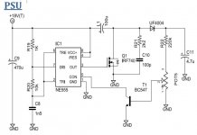
I am no SMPS designer but i keep meaning to try the power supply presented as part of this design:
GTFO - Full tube high-gain pedal (2x 12AX7)
Granted it's for a guitar effect pedal and electric guitar guys have a different relationship with distortion that we do, but i have a friend with an EE background who assures me that AC inverter designs are basically just a very big 555 timer.
The FET on the output handles all the heavy lifting. The 555 just kicks it in the gate. iirc PRR goes on to describe ways of adjusting the output.
An oscilloscope may be required to test the finished amp for power supply noise and then design a filter network to strip it out before it gets to the tube.
Oh, and yes they know that L1 is mislabeled here as a capacitor. They meant 100uh. It's also explained later in the thread that the inductor can't be a toroid, and the requirements for alternate fets are discussed in detail.
Attachments
Last edited:
My preference for small compact 1-3 valve amps of a few audio watts has been fully compliant, commercial, 12VDC external supply (eg. 3-6A), and 75-150W car 'cigarette plug' switchmode inverter. Could easily use this for at least 20-30W audio amp I suggest.
No mains AC in amp, and mains ac handled by commercial compliant product. 12VDC for heaters and for input to inverter. Inverter DC output voltage preset to about 250V (this is the major 'limitation' to deal with).
http://dalmura.com.au/projects/75W%20car%20inverter.pdf
No mains AC in amp, and mains ac handled by commercial compliant product. 12VDC for heaters and for input to inverter. Inverter DC output voltage preset to about 250V (this is the major 'limitation' to deal with).
http://dalmura.com.au/projects/75W%20car%20inverter.pdf
Last edited:
I'm sure there are other ones available if you do a search on Alibaba or eBay.
I won't be too sure.. I have been eyeing on that siliconray SMPS for sometime but it is no longer in stock for a while. Searching other sites also hasn't yield the exact product so far. Did you find any similar product in Alibaba or Ebay? Perhaps it's my searching skill that is lacking.
There is a guy in my part of the woods that has been making SMPS for tube heaters and HT supplies. They are excellent and so are the SE amps and preamps he creates using his SMPS units. His latest design switches at 500khz and can supply 3A in voltages for a huge range of DHTs and IDHTs. Not cheap but truly excellent. If you are keen, I can give you his contact via PM and you can chat with him directly.
Cheers.
Cheers.
Another idea was to again use ATX power supply and add a small inverter. 12V will be good for the heaters while a cheap 75-100W 12VDC-220VAC inverter will be small enough to fit in the enclosure. I tried using one for 4 6C33 heater but after 30 minutes, it smoked. Most probably i overloaded the crappy PSU.. 🙁
Are you saying the ATX power supply failed by loading the 12VDC rails with 4x 3.3A = 13A plus warm-up overload ? What were the 12VDC output ratings?
Are you saying the ATX power supply failed by loading the 12VDC rails with 4x 3.3A = 13A plus warm-up overload ? What were the 12VDC output ratings?
12VDC x 13.2A = 158W ~ 160W.
Yes! I was surprised as well! I thought that no way the ATX PS i use was rated lower than 160W, no matter how crappy it was. Yet the fact remains: it smoked.
The transformer was very hot before it failed. The sticker on the PS said it will withstand 17A of current on the 12VDC. The two heatsinks (on the primary side halfbridge BJT and on the secondary side schottky rectifiers) were very hot as well. I did run the SMPS without any fan (just open casing on an air conditioned room).. could this be the problem? There is now a short somewhere on the primary side of the broken ATX PS that i haven't pinpointed yet. I tried replacing the BJT and transformer (since i thought this were the only primary side components that would fail from overheating) but it was still blowing up fuse. My OTL project is halted before i can solve this.
Many of the low cost ATX power supplies are rated by the same people who make 500 watt computer speakers that run from a wall wart. I have blown up more that a few. Many PC power supplies regulate the 12V #1 output and let the others fall where they may. The 17 Amp rating might be "peak" current, or it may be real. If you connect a large heater load to the 12 volt output that is in the regulation feedback loop it will try to keep the output at 12 volts during the heater warm up and possibly fail.
Check the input rectifier diodes. The non PFC units run the line voltage through a rectifier that is switchable to be a voltage doubler on 120 VAC or a FWB on 240 VAC. The chip (usually a 5 pin flat pack mounted on a heatsink) that does the switching could be fried too.
A good ATX power supply will have multiple 12 volt outputs. Some power supplies will work OK with the outputs wired in parallel, some will misbehave. I typically try to split up the heater load across several 12 volt outputs. The power supply I have has 3 different 12 volt outputs, each rated for "25 Amps". The heaters are on two of them, and the "250 watt" car inverter is on the third. My design used 4 X 13GB5's which don't draw much heater current.
In a typical PC the 12 volt supplies are the most important, since they feed the buck converters that run the CPU and GPU's. Typical draw for a Core I5 chip at full load is 1.1 volts at 70 Amps. This is split up across multiple 12 volt synchronous buck converters.
"I have thought about it but decided that should I want to go to light weight high capacity supply I would use an ISOLATED universal power factor correcting front end like the Lambda PF500-360 here:
http://www.mouser.com/ds/2/475/pr_pf-271224.pdf
To give a B+ of 360V"
The Lambda PF500-360 I have are NOT isolated!!!!
But one could be used with an isolation transformer. Isolation xmfrs are usually cheap on Epay.
But then industrial 120V/240V/480 V xfmrs are too. (for a conventional HV power supply)
Another problem with the PFC type front ends is that they do not filter out the zero crossings in the AC power, you still need a big cap on the DC side to do that.
Do a search on Tomchr here in tubes / valves, you will find he has done quite a lot of switchmode psu stuff for tubes.
Just one hint here: http://www.diyaudio.com/forums/tubes-valves/189693-universal-filament-regulator.html
I got Tomchr's regs feeding the filaments of some 813 valves. That is 10V@5Amps per reg. They do need a little bit of cooling unlike the ones feeding my 300B's.
I got Tomchr's regs feeding the filaments of some 813 valves. That is 10V@5Amps per reg. They do need a little bit of cooling unlike the ones feeding my 300B's.
Maybe Tom will chime in but I believe those are not switch mode supplies, I think they are linear regulated circuit. At one point I was looking into purchasing his updated Maida regulator boards.
EDIT: I just found Toms site and they indeed are switchmode!
Last edited:
I am wary of SMPS for audio as they can introduce an unacceptable noise spectrum.
I have not seen any of the reputable authors of tube design books ever advocating their use
Also I dont know of any good tube amp makers that use them
I had an FM tuner with a smps that introduced a click once a second and i junked it !!
I have not seen any of the reputable authors of tube design books ever advocating their use
Also I dont know of any good tube amp makers that use them
I had an FM tuner with a smps that introduced a click once a second and i junked it !!
Hi All,
Everyday Practical Electronics (May, 2014) published +-35V 125W SMPS DIY project based on TL494 design. The article is by John Clarke and is titled "The Classic-D +-35V DC-DC converter".
I believe that it is a well thought design and I was wondering if it can be adapted for 150V or even 200V output.
Please comment who have seen the schematic.
- Status
- Not open for further replies.
- Home
- Amplifiers
- Power Supplies
- SMPS for valve design