I also have an article from SiliconChip about modding ATX Power Supply to provide high B+. Basically the mod was rewinding the transformer. Someone here told me using two transformers back-to-back could work.
I tried that, but found that the voltage regulation and power level to be poor. But I may not have done it right...
Back in the days of CRT computer monitors, their power supplies did make high voltage B+ for the CRT drivers. Around 100VDC.
Last edited:
@WA2ISE --- QEX had an article maybe 10 years ago about reconfiguring an ATX power supply for voltages more convenient to our purposes. I think it's pirated all over the web.
I tried that, but found that the voltage regulation and power level to be poor. But I may not have done it right...
Back in the days of CRT computer monitors, their power supplies did make high voltage B+ for the CRT drivers. Around 100VDC.
Trial and error don't give up

you can gain some of the benefit of SMPS if you trade off efficiency by opting for a lower slew rate. this requires some heat dissipation in the switching devices as they operate in the linear area. Linear Tech developed a line of controllers with adjustable slew, and TI just rolled out recently.
the lower rate of change di/dt means lower radiated emissions, quieter operation.
the lower rate of change di/dt means lower radiated emissions, quieter operation.
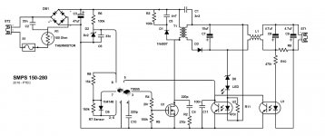
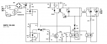
Isn't there a capacitor missing ? 😱A tested flyback solution in attachment:
For D1 better an UF4007 (faster)
Mona
Try to do away with C1, it's coupled to the mains rectifiers circuits which is not going to pass serious safety tests, eg. what if they break down?? It's considered a critical component.
Last edited:
Not quite, C1 may be required to meet EMI standard, for more please see: switch mode power supply - What does the Y capacitor in a SMPS do? - Electrical Engineering Stack Exchange
I agree, but to suppress EMI is necessary to put a capacitor between the input and output side of the power supply with a capacitance substantially higher than the capacitance in the flyback transformer.
To prevent hazards to the user, the capacitors must be designed so that short circuit failure is very unlikely, a "Y" capacitor is used for this purpose.
To prevent hazards to the user, the capacitors must be designed so that short circuit failure is very unlikely, a "Y" capacitor is used for this purpose.
You are correct, C1 in the above schematic, is often referred to as the Y-capacitor in flyback SMPS datasheets.
BingoA cap at the threshold pin of the LM555 ? Just gambling...

Mona
FYI, high voltage SMPSs tend to have worse issues with EMC.
While this might not directly affect the performance of a tube amp (which doesn't strongly rectify RF, as bipolar discrete and op-amp circuits do), the conducted and radiated emissions will very likely interfere with attached equipment in your signal chain, not to mention neighbors (some of whom might be using very important services, like shortwave aircraft navigation and emergency channels..).
As for design tips:
Any design that does not use current mode operation is doomed to failure. Sure, a voltage-mode converter can operate under lucky conditions, for decades, without happening to hit the one combination of source and load states that makes it fail. Or it can just hiccup and explode one day. Pretty dumb to leave such a liability unpatched. While hacks can be applied, the best solution is very simple: current mode feedback.
Do not use a 555. It cannot produce the range of PWM needed, without adding many components. You need two 555s (or a 556, same thing) to do that, and you still need a pair of op-amps to handle current and voltage feedback.
Better to use a discrete circuit like this, which implements current feedback:

(I wouldn't recommend it for mains input: the voltage startup circuitry will take more transistors to solve, at which point you're more than better off using a UC3842.)
Or use a proper current mode circuit, based on UC3842 or similar controllers. Or if you need more power, a TL494 (or similar) controller, but then you need an aux supply, and forward converters require even more overhead in the rectifier, due to leakage inductance and parasitic capacitance.
Tim
While this might not directly affect the performance of a tube amp (which doesn't strongly rectify RF, as bipolar discrete and op-amp circuits do), the conducted and radiated emissions will very likely interfere with attached equipment in your signal chain, not to mention neighbors (some of whom might be using very important services, like shortwave aircraft navigation and emergency channels..).
As for design tips:
Any design that does not use current mode operation is doomed to failure. Sure, a voltage-mode converter can operate under lucky conditions, for decades, without happening to hit the one combination of source and load states that makes it fail. Or it can just hiccup and explode one day. Pretty dumb to leave such a liability unpatched. While hacks can be applied, the best solution is very simple: current mode feedback.
Do not use a 555. It cannot produce the range of PWM needed, without adding many components. You need two 555s (or a 556, same thing) to do that, and you still need a pair of op-amps to handle current and voltage feedback.
Better to use a discrete circuit like this, which implements current feedback:
(I wouldn't recommend it for mains input: the voltage startup circuitry will take more transistors to solve, at which point you're more than better off using a UC3842.)
Or use a proper current mode circuit, based on UC3842 or similar controllers. Or if you need more power, a TL494 (or similar) controller, but then you need an aux supply, and forward converters require even more overhead in the rectifier, due to leakage inductance and parasitic capacitance.
Tim
I use LLC SMPS as they are applying a sine wave to the transformer primary and not square waves. This results in much less radiation.
- Status
- Not open for further replies.
- Home
- Amplifiers
- Power Supplies
- SMPS for valve design