Hi,
Anyone using SMPS for HT and Heaters for valve amps these day.
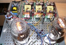
I've just lit up my first valve. Hussar! I thought I'd try it on the cheap (without all the - what you call iron).
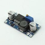
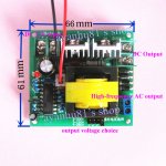
You might recognise the little blue rectangular board. They're very popular and simply generate 6.3V from a wall wart power brick. LM2596 SMPS controller chip. The square green board is a true kwality piece of kit. No output smoothing capacitors AT ALL. You have to supply your own. At least it uses a proper KA3525 chip so there's less chance of it exploding than a home brew device. I have mine set to produce about 235V B+.
A couple of issues that concern me though...
- When I turn on the whole thing from cold, my valve heater flashes fairly brightly for a 1/4 second, then settles down. Probably dodge regulation and I don't know what the long term effect of this might be. I suspect though that my wallet will find out.
- There is a very annoying 7.5KHz tone that appears at the output of the valve. It's +30dBV about the background level. That's right, I wrote thirty dBV. You can hear it as a whine. What could it be? I don't think that the B+ supply switches at that low a frequency, and harmonics only get higher than the fundamental, rather than lower.
At least the valve works. Small moves, Ellie. Small moves.
Attachments
I cheat a bit with valve power supplies.
I use two back to back transformers.
The first transformer gives 12VAC for preamp heaters.
The 12VAC is then fed into a backwards transformer of 18VAC.
This gives 160VAC which can be rectified for 230VDC.
Its a cheap way of doing it.
No reason why the first transformer shouldn't supply 6.3VAC if you use low voltage heaters.
An externally hosted image should be here but it was not working when we last tested it.
An externally hosted image should be here but it was not working when we last tested it.
Last edited:
Nigel, why do you have 4 diodes in the supply side of your schematic? I see this a lot. Isn't it simpler to just use a whopping industrial bridge rated to 100A? Your amp is expensive and not a commodity item. Surely it can't be down to cost?
100 AMPERES? 😱😱😱😱😱Nigel, why do you have 4 diodes in the supply side of your schematic? I see this a lot. Isn't it simpler to just use a whopping industrial bridge rated to 100A? Your amp is expensive and not a commodity item. Surely it can't be down to cost?
That preamp uses less than 10 milli Amperes.
The Industry Standard diode bridge for large Tube amplifiers is based on 1A rated 1N4007 diodes, go figure.
Hundreds thousand amps use them, for the last 40 years or so, I guess they must do their job fine 🙂
I use two back to back transformers.
Back to back only works at preamp levels - it sags to much at power amplifier current draws.
This is common with some early type valves, its because the resistance of the heater wire is low when cold and only rises to it operating value when hot.When I turn on the whole thing from cold, my valve heater flashes fairly brightly for a 1/4 second, then settles down. Probably dodge regulation and I don't know what the long term effect of this might be. I suspect though that my wallet will find out.
Shoog
This is common with some early type valves...
Mine are CV4014s. Are you implying that this does not happen with all valves? I thought that it was a fundamental property of metal filaments to have inrush from a cold start. I take it that I should include a resistor to prevent premature burn out?
Nigel, why do you have 4 diodes in the supply side of your schematic? I see this a lot. Isn't it simpler to just use a whopping industrial bridge rated to 100A? Your amp is expensive and not a commodity item. Surely it can't be down to cost?
The diodes need to be high speed to stop switching spikes.
The current used is only about 20mA so a 200amp bridge is complete overkill.
The two cheap transformers make the preamp/mixer quite cheap.
I am not certain how, but this is designed out in later valves. My current main amp has some Telefunken valves and they all do this.Mine are CV4014s. Are you implying that this does not happen with all valves? I thought that it was a fundamental property of metal filaments to have inrush from a cold start. I take it that I should include a resistor to prevent premature burn out?
There is no need to be concerned and no special precautions are necessary. If you want to avoid it then applying a Constant Current heater supply is the only solution.
Shoog
Well it scared the hell out of me. I thought, "oh fiddle sticks! Another project blowed up". The over current really has no detrimental effect vis a vis life expectancy?
This is going over old ground, but isn't there opinion that a constant current heater supply might not light up a filament? The scenario is that a constant 300mA feed to a 300mA heater is insufficient to generate the initial heating effect, which in turn fails to raise the resistance to generate more heat, and so on. The upshot being the filament stays cold whilst running at full (but no more) current??? Is this an old wive's tale?
This is going over old ground, but isn't there opinion that a constant current heater supply might not light up a filament? The scenario is that a constant 300mA feed to a 300mA heater is insufficient to generate the initial heating effect, which in turn fails to raise the resistance to generate more heat, and so on. The upshot being the filament stays cold whilst running at full (but no more) current??? Is this an old wive's tale?
Well it scared the hell out of me. I thought, "oh fiddle sticks! Another project blowed up". The over current really has no detrimental effect vis a vis life expectancy?
This is going over old ground, but isn't there opinion that a constant current heater supply might not light up a filament? The scenario is that a constant 300mA feed to a 300mA heater is insufficient to generate the initial heating effect, which in turn fails to raise the resistance to generate more heat, and so on. The upshot being the filament stays cold whilst running at full (but no more) current??? Is this an old wive's tale?
I really doubt this scenario so I class this as an old wives tale.
Shoog
The scenario is that a constant 300mA feed to a 300mA heater is insufficient to generate the initial heating effect, which in turn fails to raise the resistance to generate more heat, and so on.
Filaments don't have such giantic temperature dependancy. However close.
When I turn on the whole thing from cold, my valve heater flashes fairly brightly for a 1/4 second, then settles down. Probably dodge regulation and I don't know what the long term effect of this might be. I suspect though that my wallet will find out.
There is a little part of the filament that is outside of the cathode, hence can heats up faster. Since most of the filament heats up slower, showing low resistance, the outside part can be overheated by the not limited excess current. A series resistance and higher voltage may help.
It's +30dBV about the background level. That's right, I wrote thirty dBV
+30dBV is 31.6V. Are you sure you wanted to wrote this? Isn't it "+30 dB above the background"? (That is about 100 nW of acoustic power in a typical quiet environment.)
The switching freq is probably high enough not to be perceptible, but Pulse Width (Duty Cycle) is modulated trough the control loop. This control loop can be unstable, and may generate audible noise in PW.
Last edited:
- Status
- Not open for further replies.
- Home
- Amplifiers
- Power Supplies
- SMPS for valve design