Here's hoping that this will get the ball rolling..
HT+ and heater supply on one module using SG3525 PWM controller. Mind you, this is my first time designing SMPS so flaws or mistakes are likely to be found. Output voltages may need some common-mode Chokes for extra filtering. For transformer, i'm using ETD39 core which should be good enough for 150-200 Watts. I haven't calculated yet the number of turns required for both the primary and secondaries nor the wire diameter. It was decided that closed-loop monitoring should be done on the HT+ secondary, not on the filament heater as i believe filament heaters are not finicky. Heater supply was decided at 12.6V because it's easier to drop to 6.3V or any other lower value than to do the other way around.
For now, let's call this schematic as iBite PSU, because it does if you're not careful. Comments anyone? Also, does anyone know a good supplier for ETD39 core+bobbin?
edit: on a second thought, heater supply should be able to float to cope with max cathode-heater voltage difference limitation.. So it's better to leave the negative off the GND. All the more reason to monitor the HT+ instead of Heater supply.
Last edited:
🙁 I forgot the fact that on main power lines, Earth and Neutral are practically connected together at our fuse box.. that would directly connect GND to N on the schematic.. which means i'm bypassing the negative side of the rectifiers.. and causing more problems. The solution i think would be to simply move GND to the negative side of the rectifier and tap the SG3525 zener voltage from the 470uF/220V cap junctions.
Last edited:
Ballpencil,
It would be better to ask the mods to delete your schematic, I believe.
Even if it worked (it will not, from the start because the switching FETs gate and sources are not correctly referred), it would be deadly to build it because there is no isolation between the PWM controller and the raw rectified mains supply.
This is too dangerous to work on or use. It is also in violation of the Forum Rules (Note 2 about transformerless circuits).
http://www.diyaudio.com/forums/site-announcements/167561-diyaudio-rules.html
Yes i have thought about that rule.. even if we isolate the PWM, those caps would still need to be on the direct mains. Anyway, rules are rules. I'll ask mods to delete..
Wow, Sparked up a few response about a working design.
I understand I could use a convectional linear supply to develop Plate HT, Heaters and bias rails however, thought the SMPS would provide better efficiency, size and most importantly easy to change without transformer rewind.
First off, I want to make up Tube matching setup and like to set HT to the correct Plate voltages for testing and matching.
I've got the 2004 issue of Silicon Chip Mag showing how to modify a ATX Power supply but I'm not all that excited in the modified design.
Ballpencil,
Like your design have you tried this one out to see if it works?
Last edited:
Ballpencil,
Like your design have you tried this one out to see if it works?
No it won't work as pointed out by Rod Coleman. Both MOSFET source isn't referenced to GND. I'm still waiting for mods to delete the circuit. I've informed moderator Jason.
No it won't work as pointed out by Rod Coleman. Both MOSFET source isn't referenced to GND. I'm still waiting for mods to delete the circuit. I've informed moderator Jason.
Hi,
why not cut the potentiometer from the secondary side, and use a TL431 + optocoupler for the regulation feedback? Then you will be able to fully isolate the two sides. Only the MOSFET source GND referencing need to be sorted out.
 Schematic removed.
always worth watching.
I have on the drawing board a buck/boost converter which uses the MC34166 -- only because I have several tubes of them. if you have a high power wall wart, whether it's 5V to 24V you can derive 6.3, 12.6, 5.0 etc. It switches at 70kHz, can do 4A and is over-current protected. I will have boards for these in November.
For a HT SMPS you have to be very mindful of the insulation. I thought to make one using Linear's low-noise driver chips but haven't had the time to finish up.
As always, Jim Williams (RIP) did a nice video for Linear which is on youtube: Low Noise, High Voltage DC/DC Converters - Linear Technology - YouTube
Williams wrote several application notes on HV switchers. The LTC chips shape the output of the switching transistors so that they pass through the linear region. There's an energy expense for this in terms of thermal losses.
12VDC x 13.2A = 158W ~ 160W.
... I did run the SMPS without any fan (just open casing on an air conditioned room).. could this be the problem?
definitely, yes, this is the problem...
you cannot run ATX PS anyway near it's rated output without fan.
maybe at one fifth of rated load, no more - and open case doesn't help much,
actually even with fan the case must be closed for heavy load, otherwise most of the airstream is lost or does not get to all the parts which need it.
every power component in there needs forced air cooling:
e.g. 17A on a forward xfrmr at 50% DC would have to be designed for some 35A which requires a 6mm thick wire to stay within 60C over room temp, and that is not the case.
at half of rated power you can possibly throttle the fan, maybe run it on 5V instead of 12 if it isn't regulated, but some fans don't start up safely, so 7v may be better.
at full output it needs to be fully on however - and noisy.
The Jim Williams SMPS app notes are excellent
One includes a very low noise design which is quite complex however
RIP Jim you were an analog design genius
One includes a very low noise design which is quite complex however
RIP Jim you were an analog design genius
Subscribing. Given that tubes are very inefficient, i think SMPS is a good match to help keep the running cost down. I would love if we can come up with our own design..
There was a seller on Ebay with 250VDC nixie power supply module, fed from mains and isolated. I bought four units (regretted not getting more) for less than USD50. Power output is only 25W, so max current is 100mA which is good enough for one channel push-pull amplifier of 7-8 Watts. I use it on my 6FD7 PP amp.
I also have an article from SiliconChip about modding ATX Power Supply to provide high B+. Basically the mod was rewinding the transformer. Someone here told me using two transformers back-to-back could work.
Another idea was to again use ATX power supply and add a small inverter. 12V will be good for the heaters while a cheap 75-100W 12VDC-220VAC inverter will be small enough to fit in the enclosure. I tried using one for 4 6C33 heater but after 30 minutes, it smoked. Most probably i overloaded the crappy PSU.. 🙁
Search again,
Follow this link: SMPS Power Supply for Vacuum Tube Amplifier Nixie Low Noise Out 250V DC | eBay
Regards
Looks like it uses a ferrite rod for the xfmr. Toroid used for the common mode choke. High e/magnetic radiation from the rod.
Lately I have been interested in SMPS, and why not, the whole world has moved towards them.
The thing I found interesting is it's a lot like amplifiers being there are so many different topologies. I knew there were a few and I was mainly familiar with buck and flyback but man I have my work cut out for me to get somewhat caught up.
Why aren't more people using them around here for low power designs? Is it the switching frequency that scares everyone off? I made a friend of mine whom is a female acoustic guitar player a little tube preamp since her acoustic guitar isn't fitted with one 😉 It's an interface between her and the house PA, it has volume/tone controls, mute/tuner out, etc... She loves it. I used an SMPS for that. I could still see a 150mV peak switch noise at just under 50kHz. One more stage of filtering did the trick. EDIT: I used a 3A SMPS for a 305mA circuit. (two 12v 150mA 12AU7 heaters and 5mA operating current.
How about just using them to power the filaments? Seems like some folks around these parts had good luck using them. http://www.diyaudio.com/forums/tubes-valves/256826-switch-mode-heater-supply.html
There is so much data on the interwebs about SMPS it's staggering. I collect "junk" (neatly mind you) to build stuff from. I always found it interesting that almost all the SMPS I see are not identical or sometimes not even close. I mean I get the idea but talk about ways to skin a cat.
Last edited:
As JackinNJ mentioned:
"Williams wrote several application notes on HV switchers. The LTC chips shape the output of the switching transistors so that they pass through the linear region. There's an energy expense for this in terms of thermal losses."
ie: Some of the LTC chips are using controlled slew rate to avoid switching noise.
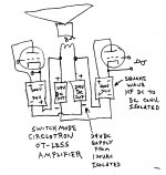
The biggest issue for SMPC is the line isolation. If you go a step further (simpler actually), one can avoid that complex issue all together and reduce ALL major expenses. See attached diagram below. A VERY simple square wave LV DC to HV DC inverter (no V regulation even, but isolated ferrite xfmr) provides B+ power AND impedance conversion for the tube(s). The LV DC can come from off the shelf (Ebay cheap) converters.
The input side of the LV to HV converter just looks like a high current tube (cathode to plate) that can run speakers directly. The tube is still driven by the usual grid to cathode signal. The DC conversion ratio is just like the turns ratio for an OT.
"Williams wrote several application notes on HV switchers. The LTC chips shape the output of the switching transistors so that they pass through the linear region. There's an energy expense for this in terms of thermal losses."
ie: Some of the LTC chips are using controlled slew rate to avoid switching noise.
The biggest issue for SMPC is the line isolation. If you go a step further (simpler actually), one can avoid that complex issue all together and reduce ALL major expenses. See attached diagram below. A VERY simple square wave LV DC to HV DC inverter (no V regulation even, but isolated ferrite xfmr) provides B+ power AND impedance conversion for the tube(s). The LV DC can come from off the shelf (Ebay cheap) converters.
The input side of the LV to HV converter just looks like a high current tube (cathode to plate) that can run speakers directly. The tube is still driven by the usual grid to cathode signal. The DC conversion ratio is just like the turns ratio for an OT.
Attachments
Last edited:
Lately I have been interested in SMPS, and why not, the whole world has moved towards them.
The thing I found interesting is it's a lot like amplifiers being there are so many different topologies. I knew there were a few and I was mainly familiar with buck and flyback but man I have my work cut out for me to get somewhat caught up.
Why aren't more people using them around here for low power designs? Is it the switching frequency that scares everyone off? I made a friend of mine whom is a female acoustic guitar player a little tube preamp since her acoustic guitar isn't fitted with one 😉 It's an interface between her and the house PA, it has volume/tone controls, mute/tuner out, etc... She loves it. I used an SMPS for that. I could still see a 150mV peak switch noise at just under 50kHz. One more stage of filtering did the trick. EDIT: I used a 3A SMPS for a 305mA circuit. (two 12v 150mA 12AU7 heaters and 5mA operating current.
How about just using them to power the filaments? Seems like some folks around these parts had good luck using them. http://www.diyaudio.com/forums/tubes-valves/256826-switch-mode-heater-supply.html
There is so much data on the interwebs about SMPS it's staggering. I collect "junk" (neatly mind you) to build stuff from. I always found it interesting that almost all the SMPS I see are not identical or sometimes not even close. I mean I get the idea but talk about ways to skin a cat.
Flyback is the work-horse of power supply topologies, whenever the output needs to be isolated from the input, for low power levels below 100W, discontinuous mode flyback (DCM) is the usually the preferred operating mode, due to it’s simpler implementation.
Flyback is the work-horse of power supply topologies, whenever the output needs to be isolated from the input, for low power levels below 100W, discontinuous mode flyback (DCM) is the usually the preferred operating mode, due to it’s simpler implementation.
Yessir, and above 100W the LLC is my personal favourite.😉
Yessir, and above 100W the LLC is my personal favourite.😉
I prefer LLC.
LLC applies a sine wave to the transformer rather than pulses like flyback.
The 2 mosfets do generate a square wave but the LLC converts it to a sine wave which his better for noise reduction.
I prefer LLC.
LLC applies a sine wave to the transformer rather than pulses like flyback.
The 2 mosfets do generate a square wave but the LLC converts it to a sine wave which his better for noise reduction.
I agree, LLC is more efficient > less EMI (another world, another power). The down side to the resonant LLC topology is its complexity and cost...
In Flyback you can improve efficiency, applying quasi resonant switching (more efficient and less EMI). A perfect 6.3v 4...5A tube heater 🙂
- Status
- Not open for further replies.
- Home
- Amplifiers
- Power Supplies
- SMPS for valve design