Member
Joined 2009
Paid Member
Yes, Q9, it is my understanding that it would be best if it were in physical contact with either Q5 or Q6 as this will give the best control over the bias current with larger changes in temperature that might occur if you drive the amp hard.
Q5 & Q6 could be strapped together on a big common heatsink and Q9 could then monitor the pair of drivers.
The problem with people attempting to copy Rode's ESP layout (and his comments on the design support this) is that without any specification for just how close Q9 should be to one or both of the drivers, there will be a wide range of errors in bias regulation, depending on whether people miss this requirement completely or just have no idea how important thermal stability is nor how the Vbe multiplier maintains it.
It's clear in this thread that people don't read the posts where this same topic is raised over and over with the many builds already begun. I guess the worst outcome is that there could be a lot of amps close to thermal runaway that one day will suddenly do just that. Hopefully without serious accidents.
Most P3a amps I've seen have had ESP PCBs and this dictates the position of Q9 which, though the air gap drastically slows the bias response, has a better tempco than a close-coupled arrangement as per D. Self's recommended design, which I adapted some years ago. I then found the P3a controller slightly overcompensated - perhaps not enough to be a problem but I think Sakis' methods may have been better for this reason and perhaps why Rode stayed with his simple, air spaced arrangement.
Look at #69 here: http://www.diyaudio.com/forums/solid-state/164756-p3a-comparison-table-long-7.html
And this tricky arrangement in #147 :http://www.diyaudio.com/forums/solid-state/164756-p3a-comparison-table-long-15.html
Eventhough what Ian said is absolutely correct ( i could add a couple of things more ) the point is that the amplifier will play well even without it ...
There is amplifiers that survived long lifes without thermal compensation like QUAD , Musical fidelity , and some others that the compensation was wrong I even recall some pro amps from Inkel now days Inter M that missed the vbe part totally ...
Obviously most amplifiers in home use will spend the 90% of duty in low listening level ...
Like testings with square wave above 40 khz ( 100 for my preamp !!! ) Offer absolutely nothing to the listener as any test to prove bandwidth above 20KHZ Still playing is one thing while seeking for perfection is another ..Test like that has to do with stability and not really listening bandwidth .
Preserving a given amount of bias versus temperature is the right thing to do while both over compensation or under compensation will effect up to a point the result ...
To me listening to an amp that has 70ma of bias in the winter time or 140 in the summer is totally out of the question ..The opposite also 70ma in the winter and 30 in the summer
Kind regards
Sakis
Last edited:
Member
Joined 2009
Paid Member
+1
Also bear in mind that the thermal sensitivity of the Vbe multiplier can be adjusted by changing the impedance of the resistor string that biases the base of the Vbe transistor. I prefer physical contact between the Vbe device and relevant power device because it's likely to be less sensitive to external thermal noise but it isn't the only way to do things.
Also bear in mind that the thermal sensitivity of the Vbe multiplier can be adjusted by changing the impedance of the resistor string that biases the base of the Vbe transistor. I prefer physical contact between the Vbe device and relevant power device because it's likely to be less sensitive to external thermal noise but it isn't the only way to do things.
Sure, domestic amplifiers have worked well enough with awful compensation but it seems pointless to DIY something that can't be optimum if it won't stay near your setting. I've read a few old articles and quotes on amplifier design where the designers always opted to overcompensate to ensure the amplifier remained safe, even when it meant bias could drop below a desirable minimum. Hitachi CFP designs and Mission Cyrus triple EF designs come to mind as more examples of rubbery compensation but I know there are many more and worse.
My own P3a breadboard assembly used a strip of 3mm aluminium about 15 x 45mm as a sink but I used a BD139 as Q9, simply bolted onto one driver, as many now prefer. The overcompensation caused bias to drop (IIRC) from 75 mA to around 35 mA with a 5W sinewave output to a resistive load. I wouldn't expect domestic listeners to be using more average power than 5W but the initial (cold amp) bias current had to be about 90 mA to have useful and safe bias levels under ambient conditions in this climate, where the annual range is 4-40C.
It seemed under control though and way better than Q9 just being somewhere on the PCB but still wasn't my idea of a good, reliable arrangement for consistent SQ. I did modify the Vbe multiplier to reduce tempco to only half that variation but other than shunt it with a resistor, I don't recall all I tried.
It's an interesting feature of linear power amplifiers and because people don't look closer than what it does in general terms and simple simulations don't tell you anything useful, bias controllers remain a mystery. (Buy a book - mystery solved!) 😉
It's simply laziness..................... It's clear in this thread that people don't read the posts where this same topic is raised over and over with the many builds already begun.
Members in their hundreds refuse to give their project the reseacrh it deserves.
They want instant gratification, instead of having to "work" for it.
It a sign of our modern times !
I don't think so................. the thermal sensitivity of the Vbe multiplier can be adjusted by changing the impedance of the resistor string that biases the base of the Vbe transistor.................
Teach me.
Members in their hundreds refuse to give their project the reseacrh it deserves.
Very wise Andrew ...Members will have to include both designers and diyers
Kind regards
Sakis
Very wise Andrew ...Members will have to include both designers and diyers
Kind regards
Sakis
Member
Joined 2009
Paid Member
I don't think so.
Teach me.
Ask why do people care about the hfe of the Vbe multiplier ?
I don't.
I use the rule that applies to most ladder resistor dividers.
The current down through the ladder should be greater than ten times the current extracted to feed the tapping.
So back to tempco sensitivity?
I use the rule that applies to most ladder resistor dividers.
The current down through the ladder should be greater than ten times the current extracted to feed the tapping.
So back to tempco sensitivity?
Member
Joined 2009
Paid Member
The bias ladder can be set up so that the base current generates a voltage drop - but I've never exploited that, in fact I don't know if it provides enough adjustment. But I have found people specifying high-beta Vbe transistors as a means to improve bias accuracy - my Pioneer HT receiver uses high-beta Vbe transistors for example.
What I have considered is this: the voltage drop across the Vbe bias ladder is generated by the steady flow of VAS current through it (it's bypassed with a cap usually so it's only a dc system). The more current that flows the larger the voltage drop and the higher the bias for the output stage. The current through the ladder is shunted by the Vbe multiplier - when it warms up it shunts more current away from the ladder and the voltage drop across the ladder is reduced and hence the bias for the output stage is reduced.
What you can do is to vary the proportion of current that passes through the ladder vs the transistor to determine how much influence the transistor will have over the bias when it's conductance changes with temperature. If the transistor is set up to shunt a large proportion of the VAS current it has more influence than if the transistor is set up to shunt a small proportion. Through this choice you can influence the sensitivity of the VAS.
Last edited:
I'll need to think about that for a while longer.
First thought is that it sounds wrong.
The Vbe multiplier is actually a Voltage regulator.
The output voltage of the regulator is the Vbias.
That Vbias depends on the Tj and that must be influenced by Pq of the transistor.
But we swamp that Pq by attaching the regulator to the "changing temperature device" that needs to be monitored.
We end up with a Vbias that mimics the tempco of the output stage.
Yes, Q9, it is my understanding that it would be best if it were in physical contact with either Q5 or Q6 as this will give the best control over the bias current with larger changes in temperature that might occur if you drive the amp hard.
Hello Bigun,
Thank you for your advice. I tested the amp as per build. Bias at 75mA and DC offset about 1 to 2mV at both channel.
Dead quite at idle. No hiss or hum at speaker. Been running it for almost half a day. The heatsink stays cool (very slight heat).
You are right, the sound is amazing for such a simple circuit.
Regards.
I had thought only in terms of electronic control around the Vbe multiplier but consider that the CFP driver circuit can be a very small thermal mass and circuit to control. You only have to use a range of driver heatsink sizes or transistor package or mounting to greatly alter the range of Vbe for the same driver dissipation. That alters tempco according the Vbe V temp. characteristic, just as certainly as a voltage divider, because you are varying the system heat loss.......So back to tempco sensitivity?
Consider what would happen if you tied the drivers and Q9 independently to a large heatsink that never rose more than a few degrees above ambient. Bias would probably be more in tune with the seasons than the output stage 😀 but contrast that with no heatsink and Q9 thermally bonded to one driver. A bit more sensitive, no?
Well, as I remember, it was the heatsink I eventually changed to get a better tempco, so I'll be careful now to only suggest a certain size arrangement that worked well enough for me, or others may have worse problems - not that we all think to check stability after initial setup.
I'll need to think about that for a while longer.
First thought is that it sounds wrong.
The Vbe multiplier is actually a Voltage regulator.
The output voltage of the regulator is the Vbias.
That Vbias depends on the Tj and that must be influenced by Pq of the transistor.
But we swamp that Pq by attaching the regulator to the "changing temperature device" that needs to be monitored.
We end up with a Vbias that mimics the tempco of the output stage.
Bigun describe it well. Bias voltage is sum of voltages over resistors. It is regulated by transistor Vbe on the be resistor, as current through cb resistor is sum of be resistor current and transistor base current.
If temperature rises, Vbe drops and decrease current. The change is multiplied by (res cb + res be)/res be ratio. We assume that base current is small enough, as hfe rise will decrease base current, and it has counter effect.
Last edited:
...We assume that base current is small enough, as hfe rise will decrease base current, and it has counter effect.
Sorry, wrong statement. Decreased base current (in view of raised hfe ) actually decreases bias voltage.
Last edited:
Member
Joined 2009
Paid Member
You are right, the sound is amazing for such a simple circuit.
It makes for a fun hobby doesn't it 🙂
If you have valuable speakers you might want to add a dc speaker protection circuit next. You can get them on eBay or build your own. It would be a nice little project to build your own - I favour the approach that uses two N-type MOSFETs to make a solid state relay, controlled by a optovoltaic device. There are a few designs around that use that approach, or use regular relays.
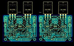
Alex mm PCB corrected
Hello DIYers
Here is Alex mm sir P3A PCB from post #90, with some correction such as D1 polarity, Some capacitors polarity, Q9 is BC 546, not BD139.as per Orignal schematics of Rod Elliott sir.Is R15 & C7 Connection is right, I think C7 is connected op through r15.Please look and give any suggestion.
Thanks
Attachments
Last edited:
- Home
- Amplifiers
- Solid State
- Rod Elliot P3A Layout - Critics