So potential is there to make a power-amp(ish) if one can find a good OPS
Maybe 🙂 I need to think about that.
I can see why you would call that a common-base driver. I would call it a cascoded common-emitter VAS. I would say the cascode itself is a common-base stage. I guess it is fair to call it the driver because it dissipates most of the power used to drive the OPS.
Just a nonstandard way of looking at it.
Just a nonstandard way of looking at it.
Back to the Mos-Fet line buffer.
Unfortunately the shape of the quasi saturation knee playes a role in that circuit.
There is no way to make the N-channel and the P-channel fully symmetric with inserting a resistor in the N-channel source.
It cancels the offset but does only work well at higher output.
Unfortunately the shape of the quasi saturation knee playes a role in that circuit.
There is no way to make the N-channel and the P-channel fully symmetric with inserting a resistor in the N-channel source.
It cancels the offset but does only work well at higher output.
Here are the measurements.
Joachim,
The blanket is too short...
This resistor is too big, and degenerates the mosfet by too much. If using smaller resistor it would not bring the gates to the same turn on point.
Did you try the diode instead of a resistor.. it may get you much closer to both destinations...
Last edited:
What 'blanket' is too short?
A situation of this resistor being the right size to adjust for opposite gate potantial, is too big and degenerates the mosfet too far.
And if you select a resistor that brings you to the same gain slope for opposit devices, you end up short on the VGS off.
Attachments

A situation of this resistor being the right size to adjust for opposite gate potantial, is too big and degenerates the mosfet too far.
And if you select a resistor that brings you to the same gain slope for opposit devices, you end up short on the VGS off.
O.k. I get it 'a way of saying' way of saying??? - ???? Weblio?? 🙂
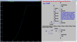
Equalizing the N and P-Channel Mosfets 🙂
P.s. If equal input (gate) impedances are important then use a Rgate resistor on the P-Channel mosfet equal to {rshift} 🙂
P.s. If equal input (gate) impedances are important then use a Rgate resistor on the P-Channel mosfet equal to {rshift} 🙂
Attachments
Last edited:
That is kind of cool, isn`t it ?
https://www.google.com/search?q=coo...S8ygOe3YLoCg&ved=0CAkQ_AUoAg&biw=1680&bih=972
Equalizing the N and P-Channel Mosfets 🙂
P.s. If equal input (gate) impedances are important then use a Rgate resistor on the P-Channel mosfet equal to {rshift} 🙂
No reactions? Constructive or otherwise critique? It is rather silent here the last few days 🙂
I knew it whould happen one day.
Measuring ultra low distortion with a distorted input signal :Total Harmonic Distortion Test Circuit Eliminates Need for External Filters | EEWeb - Maxim Tech Community
This is the diffence test with gain.
It does not require expensive equipment.
Measuring ultra low distortion with a distorted input signal :Total Harmonic Distortion Test Circuit Eliminates Need for External Filters | EEWeb - Maxim Tech Community
This is the diffence test with gain.
It does not require expensive equipment.
try to simulate the circuit with IRF510 IRF9510 mosfets as modulated current sources..
What would you expect to happen? The nice thing of the 3306's is the low capacities involved. In the given buffer stage it makes no sense (to me) to use power devices. The 3306's do fit the job (size) 🙂
Last edited: