Member
Joined 2009
Paid Member
The BOM is correct and reflects the as-built version I have.
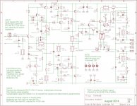
The schematic shown in post 407 appears to be incorrect - it looks like I took a slightly older version and updated it with the LED fix to create the pcb gerber files that I posted there. I'll have to update the parts values on it. Watch this space...
The schematic shown in post 407 appears to be incorrect - it looks like I took a slightly older version and updated it with the LED fix to create the pcb gerber files that I posted there. I'll have to update the parts values on it. Watch this space...
Last edited:
Thanks! 🙂
Can you confirm that all resistors (not the 1W ones) can be 1/4W except R14 and R18 that should be 1/2W?
Also C10 and C11 could be 68pF for better sound?
Can you confirm that all resistors (not the 1W ones) can be 1/4W except R14 and R18 that should be 1/2W?
Also C10 and C11 could be 68pF for better sound?
Last edited:
Member
Joined 2009
Paid Member
I've updated the schematic with the values from the BOM (the values on the schematic posted in 407 will work too but they aren't the final values I settled on and I recommend using the final values I settled on) - thanks for spotting that Paulo - team work is always better!
Correct.
In reality it will be inaudible, 100pF is fine if that's what you have on hand. That's what I used. But you can try the smaller value and see - there is scope for further experimentation with this design.
For example, the nested feedback resistor is currently 470k, what would it sound like with 100k ?? - have some fun with it, there's lots of things you can play with here if you want to explore but what I've posted is what I built and it sounds fine to me so I'm not fiddling with it anymore! 🙂
Can you confirm that all resistors (not the 1W ones) can be 1/4W except R14 and R18 that should be 1/2W?
Correct.
Also C10 and C11 could be 68pF for better sound?
In reality it will be inaudible, 100pF is fine if that's what you have on hand. That's what I used. But you can try the smaller value and see - there is scope for further experimentation with this design.
For example, the nested feedback resistor is currently 470k, what would it sound like with 100k ?? - have some fun with it, there's lots of things you can play with here if you want to explore but what I've posted is what I built and it sounds fine to me so I'm not fiddling with it anymore! 🙂
Attachments
Last edited:
Thank you, Bigun.
I'm going through the Mouser BOM one more time to ensure everything in correct and in stock. 🙂
I'm going through the Mouser BOM one more time to ensure everything in correct and in stock. 🙂
Member
Joined 2009
Paid Member
It adds up quick doesn't it, what looks like a cheap resistor at first becomes a laundry list that costs real Euros. There's very little benefit from using expensive parts in my view, the design is not very part sensitive. Compensation caps must be silva mica or c0g/np0 ceramic though.
You may want to order a few extra parts, usually there's a price break and although the total cost is higher you get some left-overs to put into your parts bin for future projects and it's good to have a couple of extra parts to replace those that fall on the carpet and become lost forever !
(remember the schematic I posted above shows the 'LED fix', D8 has no pads on the original pcb, only on the revised version - the original works fine without D8 but the LED won't light up green when in normal use - read back through the thread for details)
Last edited:
You're absolutely right, Bigun! 🙂
I never worked with SMDs before, I welcome the challenge but I hope I can see the parts without a microscope!
I noticed one more thing: the package size for C17, C19 is 1812 but the part number is of a package 0805...
I never worked with SMDs before, I welcome the challenge but I hope I can see the parts without a microscope!
I noticed one more thing: the package size for C17, C19 is 1812 but the part number is of a package 0805...
Last edited:
Member
Joined 2009
Paid Member
Another good catch: C17 and C19 are optional bypass caps. I included the pads in there on the pcb as an option. I chose not to populate them but I keep them on the BOM as others may have a different opinion. The pads are to suit an 1812 SMD part; you can use values anywhere in the range 0.1uF to 10uF (100V rating) for this purpose. A quick look at digikey - there are dozens of choices available, e.g. 445-1411-1-ND
Last edited:
Member
Joined 2009
Paid Member
I had a few questions about the large caps on the board. Let me add a few notes here that may help with some of the questions.
The large caps are in a C-R-C filter arrangement. The first C acts as the filter reservoir for the off-board bridge rectifier. The second C is the return current path for audio on the power rails. The R provides a degree of separation between these functions and acts to further reduce ripple on the power rails.
If you want 63V rated caps they are available from Digikey. For example:
United Chemicon snap-in: CAP ALUM 4700UF 63V 20% SNAP Digikey: 565-2691-ND
Nichicon snap-in: CAP ALUM 4700UF 63V 20% SNAP Digikey: 493-7290-ND
The caps I used are Cornell Dublier SLPX472M050A7P3, CAP ALUM 4700UF 50V 20% SNAP Digikey: 338-1626-ND
Primarily because they are cheap and good quality (rare combination?) but they have a high surge rating of 63V which I suggest might allow their use with nominal 50V rails - data sheet attached.
Attachments
Last edited:
Thank you Bigun. 🙂
I wish I could use some caps I have with me but they are 25mm diameter so a little big for the board.
On the other hand there are 6800uF that are only 22mm, that makes possible to use a little more filtering which I think is always good😉
I wish I could use some caps I have with me but they are 25mm diameter so a little big for the board.
On the other hand there are 6800uF that are only 22mm, that makes possible to use a little more filtering which I think is always good😉
Caps
I think I will use 2Pc something like these on the board.
2 X Nichicon Super Through KG 1000uF 63V FOR Audio Electrolytic Capacitor | eBay
I will use jumper instead a CRC on the board and I ad a capacitor bank like 4x10 000uF if I go with 63V.
If I use only 50V caps I have some Panasonic 18 000uF and I will use 4 of that as CRC set up.
I will see, look like the caps one of the last think to worried about.
The whole kit must be ordered from Mouser because the SMD parts or not the usual Parts Connexion resistors, caps size need here.
I used to order my stuff from Parts Connexion, but not for these amp.
Still exited to build but I think it will take a while until I figure it out the best solution.
Greetings
Member
Joined 2009
Paid Member
I recommend Digikey, they provide a) cheap shipping to Canada, b) v. fast turnaround, you have the parts in a day or two, c) no fakes, d) competitive prices (I looked a few times at Part Connexion - very expensive)
It might make life much easier to just buy the capacitors I used, only the price of a good quality beef burger.
And the cost is forgotten once you listen to your favourite songs on this amplifier 🙂
Have fun !
It might make life much easier to just buy the capacitors I used, only the price of a good quality beef burger.
And the cost is forgotten once you listen to your favourite songs on this amplifier 🙂
Have fun !
My boards arrived today. Thanks.
I will get some parts ordered this coming week. Looking forward to it,
Blessings, Terry
I will get some parts ordered this coming week. Looking forward to it,
Blessings, Terry
I recommend Digikey, they provide a) cheap shipping to Canada, b) v. fast turnaround, you have the parts in a day or two, c) no fakes, d) competitive prices (I looked a few times at Part Connexion - very expensive)
It might make life much easier to just buy the capacitors I used, only the price of a good quality beef burger.
And the cost is forgotten once you listen to your favourite songs on this amplifier 🙂
Have fun !
Thanks for the information,
the BOM you share that contain the Digi-Key part
All the semiconductors I have from good source direct from ON semi etc.
Only I want to know can I use IRFP610 Q14 & Q16, I do have some left over from Pass projects.🙂
If yes all I need the resistors, caps and other small components
Greetings G
Member
Joined 2009
Paid Member
I think you mean IRF610 (no 'P') ? - this doesn't look very suitable, the Rds on resistance is too high and current rating too low. But new one from Digikey are not so expensive, just keep them away from static shock until installed in the pcb.
Tom,
Check R2 is grounded, with other side on base of Q1, then set VR1 so there is around -6V wrt ground on emitter Q2, and -12V wrt ground on the zener.
Much of this problem is generated by Q2 VR1 setting, I believe. You should have around 6V across R6 (1K5) and this is around 4mA.
Verify that there is 0.63V across R4.
Cheers,
Hugh
Replace 5551, Q1.
Then set bias gen VR2 to MAX resistance to minimise output device current.
Hugh
Ok finally got my hands on some parts to try the above.
I've replaced Q1 and the good news is that fuses aren't blowing any more.
When I powered on, I saw a small puff of smoke emanating from what appeared to be the speaker protection area. No fuse blew though.
Offset is now 117mV, but I'm only reading a few mV wrt ground on emitter Q2 (the good channel is 6v exactly). Also the LED doesn't flash at all (it does on the good channel).
Emitter Q2 isn't changing as I rotate VR1. Shall I try replacing Q2?
Member
Joined 2009
Paid Member
When I powered on, I saw a small puff of smoke emanating from what appeared to be the speaker protection area. No fuse blew though.
Oh dear !
I'll see if I can help a bit more (AKSA is much better at this detective stuff than me!)
Ok I'll replace Q2. What are some key measurements I should take?
It sure does help having the working channel for reference purposes....
It sure does help having the working channel for reference purposes....
Member
Joined 2009
Paid Member
I like to have voltages measured at as many points as possible - it allows me to calculate current flow through resistors and see where the current is going and also to see what control voltages are present at the transistors.
But before I even powered up the board, if I suspected blown parts, I'd want to do some testing without power. I'd measure the resistance of resistors - even in-circuit resistance measurements can tell you something (most resistors fail open so the resistance you measure will be through the surrounding circuitry). I'd do a diode test type measurement of the transistors (much better to pull them from the board but depending on the circuit you can often still learn something). I'd do a careful visual inspection for damaged pads, tracks, foreign material, poorly cleaned solder flux, look for signs of overheated parts (resistors sometimes go brown!).
Since you have a working board you can measure resistances and do diode tests on both boards un-powered and note where they are different.
- Home
- Amplifiers
- Solid State
- TGM8 - my best amplifier, incredible bass, clear highs, no fatigue (inspired by Rod Elliot P3a)