I have been altering the value of the output filter capacitors, What is the largest value allowed ? The recommended value of 5 - 10 nf per stack, can this be increased to 20 or 30nf per stack ?
Thanks, Alex.
Been doing lots of reading on that hf cap
Haven't done any experiments yet
But from what I read it really is subject to testing
But would have thought up to 30 pf would be in range for testing
Many values will need to be tested as most of them will have a neg to no effect for sq due to a small window
Alex, 4.7-10nf per "board"..., i.e. a stack implies multiple boards. In my case I have four boards and used 22nf, which is pretty conservative.
I am using Vishay 1822 100v 100nf with 11 dac boards.
I want to try extra capacitance as increasing the value helps with resolution, ambience and purer treble. I do not want to damage anything by going too high a value ....
I want to try extra capacitance as increasing the value helps with resolution, ambience and purer treble. I do not want to damage anything by going too high a value ....
You effectively creating a low pass filter, the only thing you’ll eventually damage is the high frequencies when you get into the audible range..
You effectively creating a low pass filter, the only thing you’ll eventually damage is the high frequencies when you get into the audible range..
Good news, I think the roll off is 100khz for 5nf and 50khz for 10nf so if I go too far I will limit the HF response only but not damage the dac boards 🙂
The larger they get, the lower the HF cut off.... It is a simple 6dB/Octave low pas filter with the Rload.... so easy to calculate.... my recommendation causes a 3dB Point between 50 and 100kHz... It is very arbitrary and just pick what you like best
The larger they get, the lower the HF cut off.... It is a simple 6dB/Octave low pas filter with the Rload.... so easy to calculate.... my recommendation causes a 3dB Point between 50 and 100kHz... It is very arbitrary and just pick what you like best
Thanks Doede,
I will keep it below 600 nf. Cut off 22khz ....
This might be of interest for the pos neg cap
http://www.diyaudio.com/forums/lounge/249418-dac-filtering-technique.html
http://www.diyaudio.com/forums/lounge/249418-dac-filtering-technique.html
Hi Nige2000,
Can you elaborate a bit more what you are trying to do with the split resistors on the Outputs? The Rload value was determined to be 133 Ohm, you seem to be far off with that which will increase THD (when larger) or reduce the Output voltage at 0dBFS when lower
What are the improvements you indicated? Did you measure anything you can share?
Thanks!
Thanks Doede,
I will keep it below 600 nf. Cut off 22khz ....
not per Deck of course 😉
Finally did some testing with the Tent shunt regulators…
I build two one deck DACs to compare a straight “stock” version with a version I could experiment with…
This allowed being able to go back and forward, not needed to rely on my memory after changing the DAC …
I did a few tests in this order:
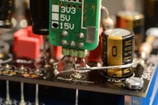
1. 8 volt Tent shunt connected at the point where the last 10uH inductor is feeding the dac circuit (of course I lifted the inductor…)
2. Remove (cut one leg) the two 47uF Cs at the corners of the DAC chip (I left the 100nF)
3. Remove (cut one leg) the two 47uF Vcom decoupling capacitors
4. Put Vcom 47uF back in place
5. 3,3Volt Tent shunt connected at the point where the 3,3V LDO is mounted (lift output pin and connect Tent at that solder pad)
So my listening experiences and conclusions are:
1. As reported by several others in the meantime, a nice upgrade which improves soundstage to be more open and clear. Also (micro) dynamics improve. For me this is close to the same level as changing from capacitors to transformer output not as dramatic, but same experience. Really worth it!
2. I could not really hear any difference. I will measure again if noise does not get out of hand. If not, this will save space for tweaks…. I would put than a 1uF film cap ate the corner positions… (arbitrary value of course, compromise between space and value I guess)
3. Well, that did not work out nicely… Sound was getting harsh edges. Like typical CD player sound… so back in… On the opposite, may be a nice Cap here will sound better? Need to try this at some point … Stijn is leading the way I believe.
4. Back to the good sound of 1 and 2
5. Well to be honest, I could not hear any significant improvement. For that reason, I would not do recommend this tweak just like that. It cost almost 80 Euro per deck extra and I believe this is not necessary. On top, the mechanical work is much easier if only the 8 Volt shunts are to be included. Feel free to disagree or comment. I believe so far no one installed the shunts in two steps and reported on the impact of the 3,3 Volt only? For me it is not needed (my opinion of course)
Thanks to all for sharing earlier comments and let’s keep tweaking
I build two one deck DACs to compare a straight “stock” version with a version I could experiment with…
This allowed being able to go back and forward, not needed to rely on my memory after changing the DAC …
I did a few tests in this order:
1. 8 volt Tent shunt connected at the point where the last 10uH inductor is feeding the dac circuit (of course I lifted the inductor…)
2. Remove (cut one leg) the two 47uF Cs at the corners of the DAC chip (I left the 100nF)
3. Remove (cut one leg) the two 47uF Vcom decoupling capacitors
4. Put Vcom 47uF back in place
5. 3,3Volt Tent shunt connected at the point where the 3,3V LDO is mounted (lift output pin and connect Tent at that solder pad)
So my listening experiences and conclusions are:
1. As reported by several others in the meantime, a nice upgrade which improves soundstage to be more open and clear. Also (micro) dynamics improve. For me this is close to the same level as changing from capacitors to transformer output not as dramatic, but same experience. Really worth it!
2. I could not really hear any difference. I will measure again if noise does not get out of hand. If not, this will save space for tweaks…. I would put than a 1uF film cap ate the corner positions… (arbitrary value of course, compromise between space and value I guess)
3. Well, that did not work out nicely… Sound was getting harsh edges. Like typical CD player sound… so back in… On the opposite, may be a nice Cap here will sound better? Need to try this at some point … Stijn is leading the way I believe.
4. Back to the good sound of 1 and 2
5. Well to be honest, I could not hear any significant improvement. For that reason, I would not do recommend this tweak just like that. It cost almost 80 Euro per deck extra and I believe this is not necessary. On top, the mechanical work is much easier if only the 8 Volt shunts are to be included. Feel free to disagree or comment. I believe so far no one installed the shunts in two steps and reported on the impact of the 3,3 Volt only? For me it is not needed (my opinion of course)
Thanks to all for sharing earlier comments and let’s keep tweaking
Attachments
Nice work Doede!
I didn't hear of anybody else testing with only shunt regs on the analog 8v.
Great to hear your findings.
It would be very nice to hear your thoughts on the effect of different caps for the vcom.
Also, would be great to see some formal testing of a current source for the bias instead of the 6k resistor as other 1794 dac makers have reported good gains there.
Thanks again,
James
Incidentally, the guys from k&k who make the RAKK dac with the current source bias suggested
" You might try a couple of different types of JFETs for this to see what sounds the best. For example, a high transconductance 2SK170 and a low/med 2N3819."
" You might try a couple of different types of JFETs for this to see what sounds the best. For example, a high transconductance 2SK170 and a low/med 2N3819."
Nice work Doede!
I didn't hear of anybody else testing with only shunt regs on the analog 8v.
Great to hear your findings.
It would be very nice to hear your thoughts on the effect of different caps for the vcom.
Also, would be great to see some formal testing of a current source for the bias instead of the 6k resistor as other 1794 dac makers have reported good gains there.
Thanks again,
James
hi James, as I have this test setup available now, I like to try some other caps as well for the Vcom....
on the current source, I like to see some circuits people actually used for this. the datasheet is very vague on the bias. still not sure if the input here will make such a difference. before putting too much time in here, I would like to see some real work and listening tests. any one knows or volunteers? 😀
Hi Doede, very intresting.
Ad 1. I always had a gut feeling about the shunts upgrade being most sensible at the analogue side. Thanks for confirming this. This might well be my next upgrade.
Ad 2. Also getting rid of the Vcc caps in combination with adding the shunt had already been suggested by Stefan and Guido from Tentlabs. So very usefull you are now confirming this too. It would be very interesting to learn how this change “measures” as well. It’s Always nice when subjective and imperial match up. 🙂
Ad 3. Stefan tried Silmic II’s in the Vcom positions and seemed to like them very much too. (My idea was really Cees Pel’s idea, btw 🙂)
Excellent news on the vcom caps testing. I look forward to hearing the results 🙂hi James, as I have this test setup available now, I like to try some other caps as well for the Vcom....
on the current source, I like to see some circuits people actually used for this. the datasheet is very vague on the bias. still not sure if the input here will make such a difference. before putting too much time in here, I would like to see some real work and listening tests. any one knows or volunteers? 😀
I think a good plan in the first instance is to exchange the resistor for a single current reference diode which matches the 0.4mA of the 6k resistor. If that makes a difference we can hear, then we know if there is potential to be unlocked here and can play with a more complex solution
I'm very happy to try this if someone can recommend a suitable component, but I'm away until the end of the month, so won't get the opportunity to test until then.
Hi Nige2000,
Can you elaborate a bit more what you are trying to do with the split resistors on the Outputs? The Rload value was determined to be 133 Ohm, you seem to be far off with that which will increase THD (when larger) or reduce the Output voltage at 0dBFS when lower
What are the improvements you indicated? Did you measure anything you can share?
Thanks!
just a bit of a compulsive experimenter really. i was reading this
http://web12491.serv4.spacequadrat.de/html/DAC_Nitro_DAB_V10.pdf
in regards the pcm1798 iv
so i thought id give it a go even though i hadn't a great variety of suitable parts
i doubt ive got the optimum combination of the two r values
ive got a 33r and a 150r in there atm
i like the sound, the difference is similar as between balanced and unbalanced compared to std config
ive very little in the way of measurements but its measuring
3.66v between neg/pos and gnd
3v between were ive taken off the signal and gnd
but maybe the 133r would be a better fit instead of 150r giving the usual 2.7/2.6v differential and then experiment with the other r value
anyway lots to test
was hoping someone would experiment and or confirm findings with me
Hi Doede, very intresting.
Ad 2. Also getting rid of the Vcc caps in combination with adding the shunt had already been suggested by Stefan and Guido from Tentlabs. So very usefull you are now confirming this too. It would be very interesting to learn how this change “measures” as well. It’s Always nice when subjective and imperial match up. 🙂
This was an easy check... could not measure any difference, so final statement
 .... 8Volt shunt without the need for the two 47uF on Vcc does it for me as excellent tweak/improvement 🙂
Last edited:
ive heard theories that suggest that what happens on the vcom is a mirror of whats on vcc. the capacitance/cap type requirement might be related to ps qualityExcellent news on the vcom caps testing. I look forward to hearing the results 🙂
im powering with lifepo4 both on analog and digital 3.3v and 8v im happy with using the smd 1 uf film caps but its a small improvement imo
ive current limiting diodes on the way from ebay but it could take a whileI think a good plan in the first instance is to exchange the resistor for a single current reference diode which matches the 0.4mA of the 6k resistor. If that makes a difference we can hear, then we know if there is potential to be unlocked here and can play with a more complex solution
ive current limiting diodes on the way from ebay but it could take a while
Have you got a link to the ones you got?
- Home
- Source & Line
- Digital Line Level
- A NOS 192/24 DAC with the PCM1794 (and WaveIO USB input)