New DDDAC Project with Reclocker - Open Questions (4 Decks vs. TentLabs Shunt Regs?)
Dear DDDAC-Enthusiasts,
After my first construction, which is running great at a friend I'm considering another build, which should be a bit advanced.
In contrast to my other design I'd like to use Ackos AKL-S03 Isolator/Reclocker, whereas I need another power supply. Moreover, I'd like to use the advanced (blue) DDDAC-Mainboard with SPDIF but need a TOSLINK input for external devices.
As I'm a bit of a newbie in audio electronics, any helpful tips are appreciated (although helpful Enrico already gave me some hints)!
I have depicted my plan in a block diagram below (maybe this is helpful for other newbies, too):
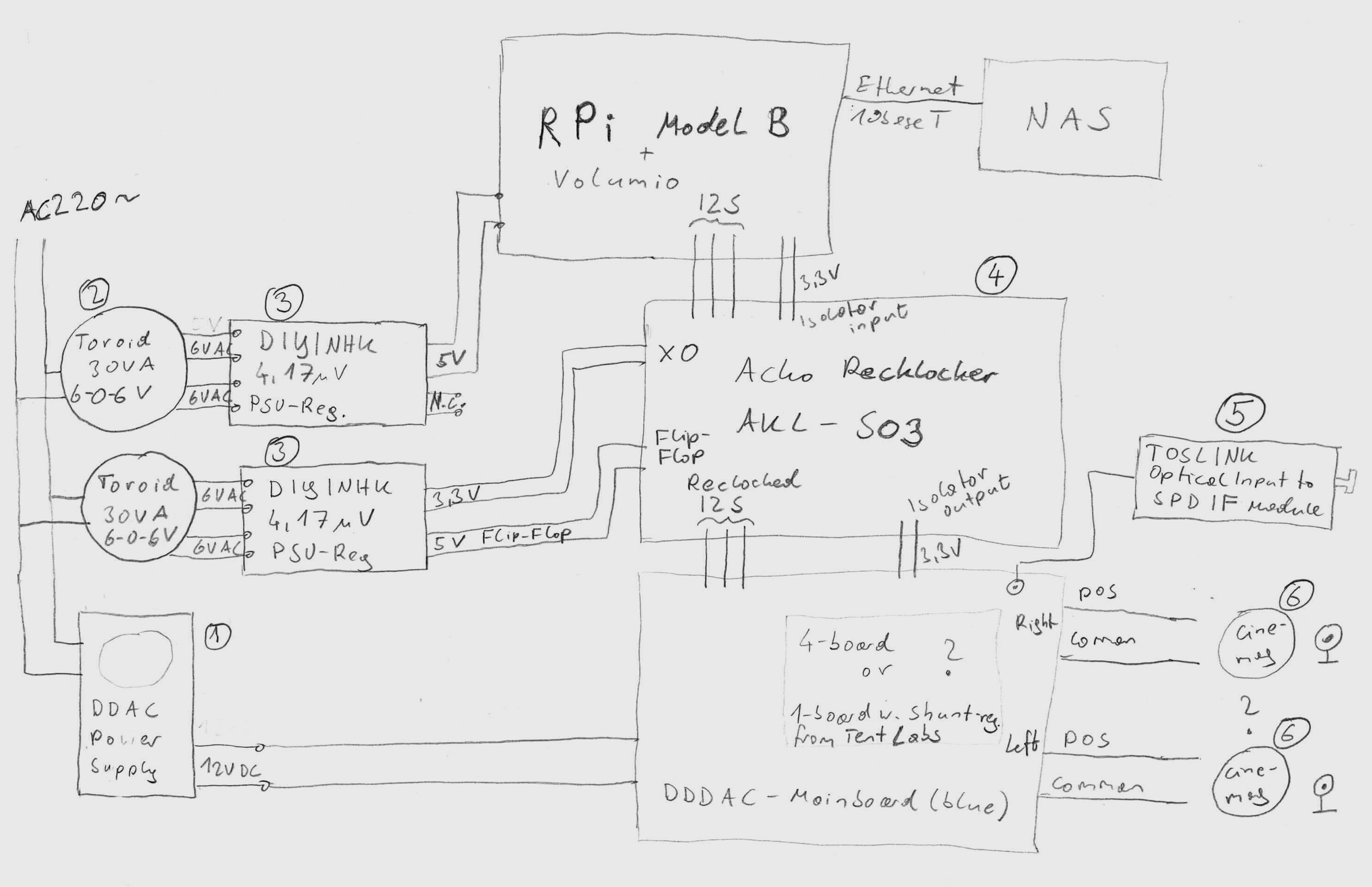
The numbers in the picture are the following devices:
(1) DDDAC Power Supply from the DDDAC Webshop
(2) Toroidial transformers from RS-Components (hopefully they are good enough ?):
Bestellen Sie Ringkern-Transformatoren Ringkerntransformator 2-Ausgnge 12 V, 6 V / 30VA Nuvotem Talema 0030P1-2-006 online bei RS fr Lieferung am nchsten Tag.
(3) DIYINHK 4.17uV Ultralow noise DAC power supply regulator 3.3V/5V 1Ax2
4.17uV Ultralow noise DAC power supply regulator 3.3V/5V 1Ax2 - DIYINHK
(4) Ackos Recklocker/Isolator AKL-S03
https://sites.google.com/site/ackodac/home
(5) TOSLINK to SPDIF converter (found on ebay):
Toslink Optical Input to s PDIF Module | eBay
(6) Cinemag output transformers from the DDDAC webshop.
Regarding this design I have the following questions:
Best Regards,
Hermann
Dear DDDAC-Enthusiasts,
After my first construction, which is running great at a friend I'm considering another build, which should be a bit advanced.
In contrast to my other design I'd like to use Ackos AKL-S03 Isolator/Reclocker, whereas I need another power supply. Moreover, I'd like to use the advanced (blue) DDDAC-Mainboard with SPDIF but need a TOSLINK input for external devices.
As I'm a bit of a newbie in audio electronics, any helpful tips are appreciated (although helpful Enrico already gave me some hints)!
I have depicted my plan in a block diagram below (maybe this is helpful for other newbies, too):
The numbers in the picture are the following devices:
(1) DDDAC Power Supply from the DDDAC Webshop
(2) Toroidial transformers from RS-Components (hopefully they are good enough ?):
Bestellen Sie Ringkern-Transformatoren Ringkerntransformator 2-Ausgnge 12 V, 6 V / 30VA Nuvotem Talema 0030P1-2-006 online bei RS fr Lieferung am nchsten Tag.
(3) DIYINHK 4.17uV Ultralow noise DAC power supply regulator 3.3V/5V 1Ax2
4.17uV Ultralow noise DAC power supply regulator 3.3V/5V 1Ax2 - DIYINHK
(4) Ackos Recklocker/Isolator AKL-S03
https://sites.google.com/site/ackodac/home
(5) TOSLINK to SPDIF converter (found on ebay):
Toslink Optical Input to s PDIF Module | eBay
(6) Cinemag output transformers from the DDDAC webshop.
Regarding this design I have the following questions:
- Are there any design flaws in the above diagram?
- How would the cinemag transformers be connected? The same as the capacitor?
- What do you think about this TOSLINK to SPDIF converter - would that work or is there any better solution?
- The most important question: My budget is limited, so I have two options:
- (a) install 4 parallel DDDAC 1794 modules or
(b) install only 1 DDDAC 1794 module and install the 4 TentLabs Shunt Regulators. As jitter should due to the Reclocker not be much of a problem, I wonder what would sound better. Any experiences in comparing these two options? - Are there any other not-so-expensive recommended tweaks I should do? I read something in the forum about using specific audio resistors somewhere?
Best Regards,
Hermann
Attachments
here it is 😎
Forgive me for being a bit dim here. I can see how then Cinemags connect to the RCA sockets but I can't see how the cinemags connect to the right and left channels of the DDDAC board!
Help
cinemag
What about this?
http://cinemag.biz/line_input/PDF/CMLI-15-15B.pdf
So: red-brown to pos-neg. (same for left or right)
Ed
Forgive me for being a bit dim here. I can see how then Cinemags connect to the RCA sockets but I can't see how the cinemags connect to the right and left channels of the DDDAC board!
Help
What about this?
http://cinemag.biz/line_input/PDF/CMLI-15-15B.pdf
So: red-brown to pos-neg. (same for left or right)
Ed
Last edited:
Recommended wiring for the cimemags goes Brown to NEG, Red to POS, then Yellow to centre of RCA, Orange to the outer of the RCA.Forgive me for being a bit dim here. I can see how then Cinemags connect to the RCA sockets but I can't see how the cinemags connect to the right and left channels of the DDDAC board!
Help
You also ideally need about a 15kOhm load at the output of the transformer. You need to work out what's needed to achieve this as it's paralleled with the impedance of your amp stage. I used a calculator - http://www.sengpielaudio.com/calculator-paralresist.htm to input the 50Kohm from my amp and 15Kohm as the desired total which gave me 21.4Kohm needed, so I went for 20kOhm resistor across the RCA plugs from centre to outer.
Thanks for this chaps, really appreciate it, but which wires go to the actual dddac motherboard? I seem to be still missing something here.
Recommended wiring for the cimemags goes Brown to NEG, Red to POS, then Yellow to centre of RCA, Orange to the outer of the RCA.
You also ideally need about a 15kOhm load at the output of the transformer. You need to work out what's needed to achieve this as it's paralleled with the impedance of your amp stage. I used a calculator - Parallel Resistor Calculator R1 + R2 = equivalent resistor R resistance circuit equiv total resistor finder made easy piggyback = parallel - sengpielaudio Sengpiel Berlin to input the 50Kohm from my amp and 15Kohm as the desired total which gave me 21.4Kohm needed, so I went for 20kOhm resistor across the RCA plugs from centre to outer.
Brown and red of each Transformer go to neg and pos of each channel from the DDDAC main board.Thanks for this chaps, really appreciate it, but which wires go to the actual dddac motherboard? I seem to be still missing something here.
You can just about make it all out here
An externally hosted image should be here but it was not working when we last tested it.
I am not too surprised at Doede's experience with the shunt regs on the digital side.
I would go back to my concern that these shunt regs are not robust enough to handle the pulse-like nature of digital power requirements. This could be made worse by being fed by another shunt reg - too many regulators cascaded is never a good idea.
I am surmising but suspect it is possible a DAC chip at times needs a current spike that the shunt cannot fully supply. It may well be that the low current BELLESONs I have installed (but have yet to hear since I ran out of silver wire, one thing after another) will suffer this same problem. I wonder if I should have got the mid-range version?
Still think it is necessary to supply the two sections separately from a non-regulated supply with lots of filter sections using a low R choke or two and 1R to 3R resistors between caps. (I am using SILMICs for the analog and the OS-COMs for the digital)
Still trying to understand why a current source would be better than a high quality resistor. Every thing I read talked about how noisy the IC current sources are compared to a resistor. I do not doubt one can make a quiet current source bu worry one would run out of space real quick. Wish I had looked at the schematic closer and had better understanding of how DACs work (as if I have much of an idea now) and had ordered some 6Ks when I got the others from TEXAS COMPONENTS. I guess one could make a current source cheaper than a TX2575. I am going to order some and hope for the EASIEST solution, though not the cheapest.
Just thought, since one can get any value they want - question to Doede, is there a best value here or is 6K as good as any?
i've ordered some expensive 6k r's for comparison hope to have tested by weekend
so we'll see
id have similar concerns over the ps, probably why i use direct from lifepo4 cells, quiet and will deal with the pulses and spikes in current demand reasonably well
Still trying to understand why a current source would be better than a high quality resistor.
The relationship between voltage and current in a resistor is a linear function.
An "ideal" CCS will pass a fixed amount of current regardless of voltage.
Think noise rejection.
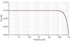
Consider the noise rejection of these two circuits...
The first is an LED fed by a resistor.
Measure the voltage reference at the junction of the LED and resistor.
You get the first graph.
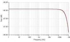
Now use a simple FET feeding the LED.
Now you get graph #2.
The first is an LED fed by a resistor.
Measure the voltage reference at the junction of the LED and resistor.
You get the first graph.
Now use a simple FET feeding the LED.
Now you get graph #2.
Attachments
And the other question is, are we supplying current TO the dac chip or limiting/controlling it's flow OUT of the dac chip from the 8V reg?
As noted previously, the voltage seems to be a constant 2.4V, so is that supply voltage a positive to ground(I don't have an operating deck to check), if so that indicates it's likely a bias current of sorts from the chip.
Could be way off, just a thought that occurred to me.
Bueller.....Bueller..............Bueller.......?
Chuz,
Drew.
Last edited:
SPM 3.3V Belleson
rickmcinnis,
I just completed my second PCM1794 DAC using SPM 3.3V Bellesons. They made a noticeable sq improvement on my first DDDAC. They only need to supply 5ma at 44KHZ and 7ma at 96KHZ versus a max output of 225ma. The voltage control specs are the same as the bigger ones on the Belleson web site. IMO the bigger ones would just be a waste of $$ and space. The OSCONS and film caps help with the fast energy release requirements by the digital side of the DAC chip.
Many thanks for your inputs Carlsor.Chanh,
The test on the Tent Shunt 3.3V regs did not indicate any use of OSCONs or a break-in period. My Bellesons needed a break-in period to sound their best. I would expect that with the OSCONs and after a couple hundred hours of music play time that the digital Vregs will be making a positive contribution to the sound quality of your magnificent DDDAC.
@stijn001 - with your feedback, I have now also ordered 22 x 220uf Elna Silmic 2 RFS to be placed at C5/C11 for each board, 47uf will come out. With this 220uf, perhaps will give better mid bass and bass extension. A more fuller analog sounding based on my experience with Doede ps where I changed one of 470uf at output to 1000uf and pleasantly surprise with mid bass improvement, very noticeable. I also ordered Shinko 5.6k 0.5W 1% to be replaced those holco 6k Iref. Hopefully this is my final tweak and am able to get on enjoying the music? It has been tooo long without this DDDAC....! 🙂
Regarding this design I have the following questions:
- Are there any design flaws in the above diagram?
- How would the cinemag transformers be connected? The same as the capacitor?
- What do you think about this TOSLINK to SPDIF converter - would that work or is there any better solution?
- The most important question: My budget is limited, so I have two options:
- (a) install 4 parallel DDDAC 1794 modules or
(b) install only 1 DDDAC 1794 module and install the 4 TentLabs Shunt Regulators. As jitter should due to the Reclocker not be much of a problem, I wonder what would sound better. Any experiences in comparing these two options?- Are there any other not-so-expensive recommended tweaks I should do? I read something in the forum about using specific audio resistors somewhere?
Best Regards,
Hermann
Hi Hermann, thanks for enthousiasm 🙂
I won't comment on the raspberry and the DIYHK as I have not used these
1. On dddac side of things this Looks OK, you must have the 1794S Version
Cinemag is connected between POS and NEG. Common is NOT used....
Isolated voltage 3,3 Volt? Is this supposed to come from the 1794S board? Please be Aware, the 1894S Version does 5Volt Output for isolation power
2.See above and other Posts
3.Take a normal optical Receiver of the TORX17x Family and connect to the SPDIF Input (see Picture below)
4. What is limited? That is a much stretched Thing 😛
5. Some say this, some say that, depending on what they have. I would say, start with one deck, see if you like it and then Change the 8Volt and listen again. Than you can decide to get to two boards and see what you like. This helps your understanding of what you are doing (it is Hobby, right?) and helps your Budget to spread over time
6. You can try some I/V (Rload) change, but do it after you build the stock version and listened first ….
Attachments

BINGO!!!! Now I understand!
Thanks !
Thanks !
Brown and red of each Transformer go to neg and pos of each channel from the DDDAC main board.
You can just about make it all out here

Reading up on CCS’s I found the following white paper which I thought was a nice introduction.
http://www.vishay.com/docs/70596/70596.pdf
I’m intrigued by the fact that the RAKK dac uses the PCM1794 and also deploys CCS’s.
There are some small form factor examples on this, inclusing PCB lay-outs.
https://mrevil.asvachin.eu/electronics/modules/#jfet_ccs
http://www.vishay.com/docs/70596/70596.pdf
I’m intrigued by the fact that the RAKK dac uses the PCM1794 and also deploys CCS’s.
There are some small form factor examples on this, inclusing PCB lay-outs.
https://mrevil.asvachin.eu/electronics/modules/#jfet_ccs
And the other question is, are we supplying current TO the dac chip or limiting/controlling it's flow OUT of the dac chip from the 8V reg?
As noted previously, the voltage seems to be a constant 2.4V, so is that supply voltage a positive to ground(I don't have an operating deck to check), if so that indicates it's likely a bias current of sorts from the chip.
Could be way off, just a thought that occurred to me.
Bueller.....Bueller..............Bueller.......?
Chuz,
Drew.
afaik its just a current reference
theres 2.4v on pin 20 regardless of what the analog voltage is and it goes to gnd via a resistor the 10k is .24ma and the 6k1 is .4ma approx
since the chip is providing the voltage that would make it a current sink
... I hope the result will please you.
But , I doubt it will be the end of it, unless you unsubscribe from DIY audio. 😉
Ok, so how is a CCS going to change that current? If the voltage is constant, the 2.4 must be the supply voltage and the CCS controls and sets the current to ground.
In my industrial control world the chip would be the current source as it's from the chip to ground. So it shall be a special CCS indeed methinks. We cannot apply a voltage to that pin to do anything, it must have a load of sorts to limit current flow.
I'm no genius I'm just spitballing here, I do not have a solution to offer, so trying to ask valid questions that can possibly solve or at least give an option to try.
Can we use the 3.3v or 8V as a supply to a fet setup somehow, or even an led by itself, perhaps an led that has a lower resistance as some voltage would be dropped across the led?
If we have a 1.8V led ohms law would tell us the current, which works out to be 1K525R, somewhat different to 6K, easy enough to setup a bench supply at 2.4V, led and resistor and measure voltage drop on resistor to confirm 0.4mA. 2.2V led would reduce the resistor again to 500R.
Worth trying? I don't have a dac so I cant, Doede, thoughts?
Chuz,
Drew.
Hi Hermann, thanks for enthousiasm 🙂
I won't comment on the raspberry and the DIYHK as I have not used these
1. On dddac side of things this Looks OK, you must have the 1794S Version
Cinemag is connected between POS and NEG. Common is NOT used....
Isolated voltage 3,3 Volt? Is this supposed to come from the 1794S board? Please be Aware, the 1894S Version does 5Volt Output for isolation power
2.See above and other Posts
3.Take a normal optical Receiver of the TORX17x Family and connect to the SPDIF Input (see Picture below)
4. What is limited? That is a much stretched Thing 😛
5. Some say this, some say that, depending on what they have. I would say, start with one deck, see if you like it and then Change the 8Volt and listen again. Than you can decide to get to two boards and see what you like. This helps your understanding of what you are doing (it is Hobby, right?) and helps your Budget to spread over time
6. You can try some I/V (Rload) change, but do it after you build the stock version and listened first ….
Ciao Doede,
Just for my understanding... Hermann would like to use the cinemag that I never have the chance to use but I have the Sowters in my DDDAC and as far I know they need 4 boards to work properly or at least a buffer as per carlsor configuration.
Are the Cinemags different from the Sowters?
Regards,
Enrico
Cinemags work fine with 1 deck. They may benefit from a buffer stage in between, but more about that later.... 😉Ciao Doede,
Just for my understanding... Hermann would like to use the cinemag that I never have the chance to use but I have the Sowters in my DDDAC and as far I know they need 4 boards to work properly or at least a buffer as per carlsor configuration.
Are the Cinemags different from the Sowters?
Regards,
Enrico
- Home
- Source & Line
- Digital Line Level
- A NOS 192/24 DAC with the PCM1794 (and WaveIO USB input)