4 X Siliconix J500 0 24mA Current Regulator Diode | eBay
4 X Siliconix J502 0 43mA Current Regulator Diode | eBay
ones close to the ti datasheets iref current draw, and the other a little over deodes current recommendation i think
really just an initial experiment to see if theres any merit in it
before i go making it complicated
though i think i might have 2SK170's here somewhere 🙁)
did you come across any schematics?
other options?
5. Well to be honest, I could not hear any significant improvement. For that reason, I would not do recommend this tweak just like that. It cost almost 80 Euro per deck extra and I believe this is not necessary. On top, the mechanical work is much easier if only the 8 Volt shunts are to be included. Feel free to disagree or comment. I believe so far no one installed the shunts in two steps and reported on the impact of the 3,3 Volt only? For me it is not needed (my opinion of course)
Thanks to all for sharing earlier comments and let’s keep tweaking
Thanks Doede for this most interesting update!
Personally, I found this a little disappointing! Nonetheless, I will continue with my 47-Shunts mod and report back my own findings.
One question, were your findings with shunts based on your very own regulated power supply?
Hi Chanh,
why not try one deck your self with and without 3,3 Volt now you have so many Shunts and decks?
YES, I used my power supply to feed the shunt...
why not try one deck your self with and without 3,3 Volt now you have so many Shunts and decks?
YES, I used my power supply to feed the shunt...
Hi Chanh,
why not try one deck your self with and without 3,3 Volt now you have so many Shunts and decks?
YES, I used my power supply to feed the shunt...
Sure will try single deck with Shunts vs standard stock (Mate's DDDAC).
I have just placed an order for Oscon SEPC. Once these arrived, will let you know our little shootout. Going to be interesting?
This was an easy check... could not measure any difference, so final statement.... 8Volt shunt without the need for the two 47uF on Vcc does it for me as excellent tweak/improvement 🙂
When I first read this I thought you were speaking of the Vcom caps - now I see it is Vcc which would make sense when using shunts. I cannot get the message to delete or I would have done that.
Last edited:
Doede's 3.3V Reg Test
I have Belleson 3.3V regs on the digital circuits of my single board DDDAC and always wondered how they compared with Tent Shunt 3.3V regs. I am surprised that Doede reported that the 3.3V Tent shunts made little/no difference in sq.
I installed the Bellesons 3.3V regs after I had installed the Salas 8V shunt reg on the analog circuits. My original build used Elna Silmics in all the analog locations. The Salas Shunt made the DDDAC sound more analog and authoritative - all good.
I was stunned at the improvement the Bellesons made on the digital circuits on the DDDAC board. Little/no change in sq on the main board. I installed 47uf organic (OSCON equiv) caps bypassed with 0.1uf film caps both at the inputs AND at the outputs of the Bellesons as suggested on their web site. The power source is unregulated 7.5-8.0VDC from a rectified-filtered 6.3VAC tube filament transformer. 44.1/16 USB signals never sounded right until I replaced the LF33s with Bellesons. I had been converting my CDs to 96/24 in JRiver with satisfactory results. Now 44.1/16 USB signals sound more musically real to me.
Anyone else have experience with the Belleson 3.3V regs?
I have them on my single deck, but didn't compare stock VS SPM...
I'm not at home now but in september i'll start serious tweaks around the Bellesons.
I'm not at home now but in september i'll start serious tweaks around the Bellesons.
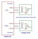
I have just received delivery of a pair of Cinemags for the DAC , I have been trawling the forum like mad trying to find some pictures of how others have installed these, but I can't find anything.
Is anyone able to explain how to wire up the cinemags and post a few pictures?
Many thanks
Is anyone able to explain how to wire up the cinemags and post a few pictures?
Many thanks
Doede's new findings with the Shunts seem a little depressing for me personally. It has somewhat damping my enthusiasm and certainly end result expectation. Prior to this I was hoping to get back the analog Vinyl sound imaging from this DDDAC with suffient love injection! My gut feel told me that it CAN for which much efforts and funding were invested.
Right now, my mod is based collectively from Stefan, and Others. I should be in the position to tell you of my finding soon.
Here are some couple photos prior the Shunts installed.
Note, all skinless caps are 47uf 25V Elna Silmic II Japan Made. I will be installing OSCon 100uf 16V just before the 3.3V shunt on digital side. As for Vcom caps, the Jensen 47uf is too big in side and I must draw a line in the sand somewhere. 🙂
Ah thanks Doede
Quick question though. What is the valve of the resister between the orange and yellow wires? And I am left with two other wires, white and black, what do I do with these?
Thanks again for your help!
James
Quick question though. What is the valve of the resister between the orange and yellow wires? And I am left with two other wires, white and black, what do I do with these?
Thanks again for your help!
James
......
Chanh, they look awesome! The problem you are having is like mine, where when increasing the nr of boards, tweaking anything becomes an increasing amount of work, even more so in your case with 11 boards. So to get exactly the sound you are after is going to be increasingly hard. But I think, by what I’ve heard the Silmic’s do in my dac, you are on the right track. And there is a suprising amount of scope for personalization at the output as well by trying different types of Rload resistors and HF filter caps, output caps etc.
Even if Doede didn’t "perceive" an audible difference adding the 3.3V shunt at the Vdd, doesn’t mean it’s not better, it is, albeit it being less of a difference then hoped for. Others did hear improvements here..
There are other things it seems you are planning looking at your boards, like splitting power supplies for the digital and analogue sides, probably analogue left/right separation as well.
By the time you are done you’ll have constructed the most “tricked-out” DDDAC (I know of anyway).
Looking at the boards. I noticed a few things.
Left channels only
- C6 is isolated, has no function anymore.
- C5 is isolated has no function anymore
- Presuming you are planning the OSCON at position C27?
- Stefan replaced C17/C23/C31 with Wima’s .068uF/63V
- Last thing, Stefan interconnected the boards for analogue power via one of the positions for C1-C4, as you populated 3 out of 4 I suspect this will be hard in your case.
Last edited:
Ah thanks Doede
Quick question though. What is the valve of the resister between the orange and yellow wires? And I am left with two other wires, white and black, what do I do with these?
Thanks again for your help!
James
black and white (it says in dutch) cut short and let them float 😀
Value is not critical. 10k - 15k was reported to be good, but you can try if it does something to your ears. No limits in value though. You can leave it out as well
Looking at the boards. I noticed a few things.
Left channels only
- C6 is isolated, has no function anymore.
- C5 is isolated has no function anymore
- Presuming you are planning the OSCON at position C27?
- Stefan replaced C17/C23/C31 with Wima’s .068uF/63V
- Last thing, Stefan interconnected the boards for analogue power via one of the positions for C1-C4, as you populated 3 out of 4 I suspect this will be hard in your case.
Thanks for the encouragement stijn001!
It would be ideal to have separate ps for digital side both left/right and again for analog side. Unfortunately there is no way around it as digital and analog share common ground. So the only logical thing to do here is to passively separate analog/digital PS from same raw unregulated ps with another passive stage for digital RC(L if nesscesary). Precisely to Stefan ideology.
Here is the logic of my layout, please feel free to correct or contribute your constructive inputs.
DAC will power by raw chokes input unregulated ps, the ps layout will similar to Stefan for digital and analog. i.e another passive filter stage for digital.
1. Digital ps supplies all digital side of DAC, including mainboard. All stock 0.1uf wima were replaced by 0.068uf 120V Vishay. No 47uf cap after the 5V shunt to delay chips as show on mainboard, any filter will be done by 0.068uf Vishay per delay chipset. Locally each board will have it own 160uf 16V OSCon SEPC at C14. C27/28 is where the 3.3V shunt will be placed like Stefan.
2. Analog side will be wired from either at (+Ve C1 caps or R1 output). An arrays 11-Decks will connect direct to raw ps. Since I do not use 470uf on main-board for analog, C5/6 are now locally part of the bank 47uf filter caps for analog. The only filter for the analog is RC, stock 22 ohms and an arrays of 5 x 47uf and stock 1uf wima. I believed local filter is always better than global filter, and also multi smaller uf caps than one bigger cap. Unless it is OSCon as ESR for them are tiny (mOhm). 🙂 8V shunt will be placed at L2, again identical to Stefan. 😀 unlike Stefan, I will stay with wima 0.1uf at around the analog DAC chips, I didn't mind the effort but concerning I might damaging the Chip with my desoldering and resoldering skills!
3. All stock signal (I2S) resistors were replaced by AudioNote Tantalum, including the 10k on main-board were also replaced by Shinko tantalum 0.5W. I/V resistors are 12 ohms AudioNote Tantalum non-magnetic, similarly to Stefan and stijn001. I like AudioNote as I could heard massive improvement on clarity and 3D sound stage on my other mods for my current tubes/valves preamp and power amp. I use Conrad Johnson pre and Bob Carver Power.
4. Behind the scene, I sanded and alcohol washed every leg of those caps and resisters before soldering on board. There were lots of patience and love there, which my mate here (Tuyen is king of diy in Western Australia) still think am one of a crazy DIYer. Not sure doing that would improve anything?!? I guess it gives me piece of mind! LoL!?!
Best,
Chanh
Last edited:
The reason I did not populate C1 was because of tent shunts 3.3V on the left. Tent shunt will generate fair bit of heat, and its placement is at C28 diagonal where the tail is laying between Vb and inlet R3, too close to C1. Over time will shorten the life of this cap due to constant heart exposure. Since C1 is not there, for consistency, C7 is also removed. 🙂Last thing, Stefan interconnected the boards for analogue power via one of the positions for C1-C4, as you populated 3 out of 4 I suspect this will be hard in your case.
Last edited:
Hi Chanh, like you say I was also concidering passively separate digital, analogue left/right with an RC, just one of many more idea’s to be tried.
Ad 1. Yes, Im following you here, I suspect 160uf is a type-O, this will be your 100uf, correct?
Ad2. Right, I get what you are proposing. One thing I would recommend you do (not just me), is maintain a big cap (close to the dac stack is better) for the analogue part, like the 470uf that was originally on the mainboard. This is an easy test you can do once you’ve put the whole thing back together again.
Ad3. Idem, I have the same experience
Ad4. I always thought peace of mind was the opposite of crazy.. 🙂
Ad 1. Yes, Im following you here, I suspect 160uf is a type-O, this will be your 100uf, correct?
Thanks, will take point 2 on board. 🙂
Yes it is 100uf 16V OSCon SEPC. Here the link, 4 Sanyo Sepc 16V 100uF OS Con Aluminum Solid Low ESR High Reliability Capacitor | eBay
Cheers again stijn001.
Chanh,
The test on the Tent Shunt 3.3V regs did not indicate any use of OSCONs or a break-in period. My Bellesons needed a break-in period to sound their best. I would expect that with the OSCONs and after a couple hundred hours of music play time that the digital Vregs will be making a positive contribution to the sound quality of your magnificent DDDAC.
The test on the Tent Shunt 3.3V regs did not indicate any use of OSCONs or a break-in period. My Bellesons needed a break-in period to sound their best. I would expect that with the OSCONs and after a couple hundred hours of music play time that the digital Vregs will be making a positive contribution to the sound quality of your magnificent DDDAC.
I am not too surprised at Doede's experience with the shunt regs on the digital side.
I would go back to my concern that these shunt regs are not robust enough to handle the pulse-like nature of digital power requirements. This could be made worse by being fed by another shunt reg - too many regulators cascaded is never a good idea.
I am surmising but suspect it is possible a DAC chip at times needs a current spike that the shunt cannot fully supply. It may well be that the low current BELLESONs I have installed (but have yet to hear since I ran out of silver wire, one thing after another) will suffer this same problem. I wonder if I should have got the mid-range version?
Still think it is necessary to supply the two sections separately from a non-regulated supply with lots of filter sections using a low R choke or two and 1R to 3R resistors between caps. (I am using SILMICs for the analog and the OS-COMs for the digital)
Still trying to understand why a current source would be better than a high quality resistor. Every thing I read talked about how noisy the IC current sources are compared to a resistor. I do not doubt one can make a quiet current source bu worry one would run out of space real quick. Wish I had looked at the schematic closer and had better understanding of how DACs work (as if I have much of an idea now) and had ordered some 6Ks when I got the others from TEXAS COMPONENTS. I guess one could make a current source cheaper than a TX2575. I am going to order some and hope for the EASIEST solution, though not the cheapest.
Just thought, since one can get any value they want - question to Doede, is there a best value here or is 6K as good as any?
- Home
- Source & Line
- Digital Line Level
- A NOS 192/24 DAC with the PCM1794 (and WaveIO USB input)