ok ill look into it,
mines reading 2.4v
i was experimenting with various resistors the one thats in it now is likely not exactly 6k
Ok I put the 6k1 back in still reading 2.4v
Can someone but a voltmeter on pin 20 please
It would seem likely that pin 20 will always be 2.4 volts.
What changes is the current through the resistor connected to it.
The stock value of 10k results in 0.24mA of current.
The optimal value of 6k results in about 0.4mA of current.
I have an unrelated PCM1794a based DAC with 5 volts for the analog half
and I got 2.4 volts on pin 20 with a 10k resistor on it.
Last edited:
Avro Arrow's post kind of puts in question whether this would benefit from a CCS. The CCS will strive to keep the current constant while other conditions may vary. It seems that the 2.4V at pin 20 is a given.
In any case, if the task at hand is to provide a CCS in place of the 6k resistor that sees a 2.4V drop over it, here are some options I see.
Firstly, the low voltage drop kind of narrows down the possibilities quite substantially. Cascode configurations, though all better than the basic ones, are pretty much ruled out. I just don't think there is enough voltage "room" for two devices to operate properly. It's a pity, because they really do improve on most facets of a CCS's performance (better rejection across a wider bandwidth, lower capacitances, etc.). Note - when I say "audio band" below, I mean more something like 10Hz - 100kHz and above.
1. CCS based on LM334. It only requires 1V to operate properly and can be adjusted for the 400uA required by the application. Non-cascoded offers more than -130dB rejection at lower frequencies (under like 2kHz), which is awesome, but that degrades quite substantially over about 20kHz.
2. You can use one of the packaged current regulating diodes available out there. I don't think the J500 series is still available, but Mouser has something like 1N5288 which regulates a nominal 390uA if biased with at least 1.05V, which 2.4V complies with. Performance is good at a rejection of about -120dB for most of the audio band, and you can't beat the ease to implement this. These are pretty much number 3 below (JFETs with g/s connected internally), without the adjusting resistor which is typically used (and improves output impedance, a good thing).
3. I like this the most because it's the most challenging, and it may be at least as good as (2) above at high frequencies and definitely better than (1) at that. Rejection is about 113dB. It's also what most people do for CCSs, though the low voltage drop requires some work in sorting JFETs. This third option is a n-channel JFET CCS with a setting resistor. The issue here is that they work best when operated at at least twice the Vgs(off) of the JFET. Also, best suited for CCSs are long gate JFETs (best rejection). I think J201 is a good option here due to the above requirements, provided the parts used are sorted for:
- Vgs(off) lower than 1.2V (may be as high as 1.5V);
- Idss comfortably higher than 400uA (may be as low as 200uA).
I'm not sure what the spread is in a typical batch, but out of some J202s and other JFETs I worked with recently, the consistency was pretty good, so...
This last one is for the tweaker. I think for a quick fix, number two is the best. In between these two is number one, which gives good performance but a bit inconsistent across a wide bandwidth (excellent LF, fine HF).
Radu.
Last edited:
Finally my Shunts arrived....
Impressive desoldering job & nice stash!
Regarding the inductor/resistor. To me it just appears to be a bit of filtering and separation/voltage drop of the power feeds to different parts of the board. But if the ripple/noise rejection of the shunts is as good as expected then my guess would be they are obsolete, also depending on what voltage you get at the shunts input. Less is more in this case.
One more comment. Stefan used lower 68nf values for the 100nf HF bypass caps across the 47nf’s on the analogue side. The Silmic’s are supposed to sound better with these. Since you seem to be going for audio nirvana, you might want to consider this.
How are you planning to power the 11 board with shunts? Presumably that will draw quite a bit more current. I can’t recall if you planned to use the Lundhall 1694’s but their optimum power handling capacity is documented as 1.5amp in series common mode. If you use the coils in parallel you can go up to 3A, which is what you might have to do. Or you could build two PS’s, one for each channel, or 4 seperating the Digital from the analogue sides as well.. 😉
Here's what Doede wrote about calculating the bias:
the rest of the investigation are here: - DDDAC 1794 NOS DAC - Non Oversampling DAC with PCM1794 - no digital filter - modular design DIY DAC for high resolution audio 192/24 192kHz 24bit
I'd been wondering about this. Thanks.
Impressive desoldering job & nice stash!
One more comment. Stefan used lower 68nf values for the 100nf HF bypass caps across the 47nf’s on the analogue side. The Silmic’s are supposed to sound better with these. Since you seem to be going for audio nirvana, you might want to consider this.
How are you planning to power the 11 board with shunts? Presumably that will draw quite a bit more current. I can’t recall if you planned to use the Lundhall 1694’s but their optimum power handling capacity is documented as 1.5amp in series common mode. If you use the coils in parallel you can go up to 3A, which is what you might have to do. Or you could build two PS’s, one for each channel, or 4 seperating the Digital from the analogue sides as well.. 😉
Thanks Stijn001!
W.r.t 68nf, I bought Vishay at partconnexion but are too big compare to Wima 0.1uf. There simply not enough room for them. So I decide to use them as filter caps for mainboard.
An externally hosted image should be here but it was not working when we last tested it.
An externally hosted image should be here but it was not working when we last tested it.
An externally hosted image should be here but it was not working when we last tested it.
As for powering the 11-Decks with Shunts, Guido has reiterated to me that 200VA is sufficient to power them. My chokes are not Lunldal, they are from Vanbar, they do 5A, 50mA at 0.23 Ohm. Hopefully they are fine?!?
Best,
Chanh
Right, yes your using the Valab's, 5A should be ample. The Wima 68nf 63v's coming in the same form factor as the 100nf. You could go for those. Mouser.com stocks them.. UPS shipment to Europe is two days..
Curious to see how your dac will turn out. You aren't planning a trip to the Netherlands by any chance, are you? I'm sure some people over here would be interested in an audition.. 😉
Brilliant info, thanks 🙂Avro Arrow's post kind of puts in question whether this would benefit from a CCS. The CCS will strive to keep the current constant while other conditions may vary. It seems that the 2.4V at pin 20 is a given.
In any case, if the task at hand is to provide a CCS in place of the 6k resistor that sees a 2.4V drop over it, here are some options I see.
Firstly, the low voltage drop kind of narrows down the possibilities quite substantially. Cascode configurations, though all better than the basic ones, are pretty much ruled out. I just don't think there is enough voltage "room" for two devices to operate properly. It's a pity, because they really do improve on most facets of a CCS's performance (better rejection across a wider bandwidth, lower capacitances, etc.). Note - when I say "audio band" below, I mean more something like 10Hz - 100kHz and above.
1. CCS based on LM334. It only requires 1V to operate properly and can be adjusted for the 400uA required by the application. Non-cascoded offers more than -130dB rejection at lower frequencies (under like 2kHz), which is awesome, but that degrades quite substantially over about 20kHz.
2. You can use one of the packaged current regulating diodes available out there. I don't think the J500 series is still available, but Mouser has something like 1N5288 which regulates a nominal 390uA if biased with at least 1.05V, which 2.4V complies with. Performance is good at a rejection of about -120dB for most of the audio band, and you can't beat the ease to implement this. These are pretty much number 3 below (JFETs with g/s connected internally), without the adjusting resistor which is typically used (and improves output impedance, a good thing).
3. I like this the most because it's the most challenging, and it may be at least as good as (2) above at high frequencies and definitely better than (1) at that. Rejection is about 113dB. It's also what most people do for CCSs, though the low voltage drop requires some work in sorting JFETs. This third option is a n-channel JFET CCS with a setting resistor. The issue here is that they work best when operated at at least twice the Vgs(off) of the JFET. Also, best suited for CCSs are long gate JFETs (best rejection). I think J201 is a good option here due to the above requirements, provided the parts used are sorted for:
- Vgs(off) lower than 1.2V (may be as high as 1.5V);
- Idss comfortably higher than 400uA (may be as low as 200uA).
I'm not sure what the spread is in a typical batch, but out of some J202s and other JFETs I worked with recently, the consistency was pretty good, so...
This last one is for the tweaker. I think for a quick fix, number two is the best. In between these two is number one, which gives good performance but a bit inconsistent across a wide bandwidth (excellent LF, fine HF).
Radu.
Could you explain in basic terms for the uneducated, what it is that these solutions offer which is better than a resistor? Is it an increase in accuracy and stability of the current draw?
I asked the K&K guys on their forum for any details about their current reference and got the following replies:
I have to pass the credit to Nige for finding this little nugget of info 😉Dave Davenport said:You have a sharp eye and a keen intellect in spotting that and assessing its worth. It is not just a simple CCS like we use elsewhere but an innovative design that took quite a bit to develop. This is only one of the several "secrets" that make the RAKK dac such an outstanding performer.
I choose to disclose the existence of a few of the innovations and choose to not disclose others. However, it would be foolish of me to give away the competitive edge of the RAKK dac by revealing the details of the innovations.
JKT said:You could replace the resistor with a simple JFET current source like the earlier RAKK DACs (1-3). Sounds better than a resistor, but not as good as the new one in the Mark IV
Chanh,
You can mount components from the bottom to make space.
Thanks Rick!
I did just that for the main board. Now am running short on Vishay 68nf if I was to apply the same concept to the three analog bypass caps at every DAC chip. I guess more caps will be ordered. 😀
An externally hosted image should be here but it was not working when we last tested it.
An externally hosted image should be here but it was not working when we last tested it.
Last edited:
r core and choke position.
Hello,
Just did connect my r-core to the mains and did do some test with the choke.
I did use a bleeder to create about 350ma current flow. Then i did put an high inductance choke with a double coil construction so very similar to the ones used here( 2733 and ll1694)
Just did connect a multimeter and measured ac level across the choke. Distance from r core to choke about 35 millimeter. SO no current flow through the choke just multimeter attached. ( 4 different positions but equal distance to the R core measured ac 0,013 0,133 0,095 and 0,006 volts)
I did connect the transformer with a variac and when lowering the voltage ( so also lowering the bleeder current) the ac voltage across the choke did go down. With 1A ( because of shunts) one should take about positioning the transformer(s) and the chokes.
There is a link in this thread somewhere but i dont know where. Everybody talking about boutique caps but nobody mounts the chokes the best way.
Because of the temporary nature of the R core test, it was not so safe to move the chokes around the R core. This time i just put close to the winding of the r core.
I wanna make a steel cap for the r core and surround it with a resin so that is why i need to know how to mount it. Of course one also needs to take care of how to mount the chokes which are close to the circuit or the output transformers.
Lundahl did tell me the field around the choke will not be big. And R core usually also doesnt have much radiation. But better be safe then sorry.
Will do more test later.
Greetings, Edward
Avro Arrow's post kind of puts in question whether this would benefit from a CCS. The CCS will strive to keep the current constant while other conditions may vary. It seems that the 2.4V at pin 20 is a given.
In any case, if the task at hand is to provide a CCS in place of the 6k resistor that sees a 2.4V drop over it, here are some options I see.
Firstly, the low voltage drop kind of narrows down the possibilities quite substantially. Cascode configurations, though all better than the basic ones, are pretty much ruled out. I just don't think there is enough voltage "room" for two devices to operate properly. It's a pity, because they really do improve on most facets of a CCS's performance (better rejection across a wider bandwidth, lower capacitances, etc.). Note - when I say "audio band" below, I mean more something like 10Hz - 100kHz and above.
1. CCS based on LM334. It only requires 1V to operate properly and can be adjusted for the 400uA required by the application. Non-cascoded offers more than -130dB rejection at lower frequencies (under like 2kHz), which is awesome, but that degrades quite substantially over about 20kHz.
2. You can use one of the packaged current regulating diodes available out there. I don't think the J500 series is still available, but Mouser has something like 1N5288 which regulates a nominal 390uA if biased with at least 1.05V, which 2.4V complies with. Performance is good at a rejection of about -120dB for most of the audio band, and you can't beat the ease to implement this. These are pretty much number 3 below (JFETs with g/s connected internally), without the adjusting resistor which is typically used (and improves output impedance, a good thing).
3. I like this the most because it's the most challenging, and it may be at least as good as (2) above at high frequencies and definitely better than (1) at that. Rejection is about 113dB. It's also what most people do for CCSs, though the low voltage drop requires some work in sorting JFETs. This third option is a n-channel JFET CCS with a setting resistor. The issue here is that they work best when operated at at least twice the Vgs(off) of the JFET. Also, best suited for CCSs are long gate JFETs (best rejection). I think J201 is a good option here due to the above requirements, provided the parts used are sorted for:
- Vgs(off) lower than 1.2V (may be as high as 1.5V);
- Idss comfortably higher than 400uA (may be as low as 200uA).
I'm not sure what the spread is in a typical batch, but out of some J202s and other JFETs I worked with recently, the consistency was pretty good, so...
This last one is for the tweaker. I think for a quick fix, number two is the best. In between these two is number one, which gives good performance but a bit inconsistent across a wide bandwidth (excellent LF, fine HF).
Radu.
cheers rax thats great
i suppose we would like to be able to vary the current a little, so option three would likely suit.
difficulty finding 1N5288 anyway
could you point us towards a schematic, bom please
thx again rax
DDDAC finished - A short report
Hi,
I just wanted to let you know that we (a group of friends in Austria/Vienna) just successfully finished our little DDDAC-Project. The setup is as follows:
- DDDAC Mainboard (red version)
- One DDDAC PCB
- DDDAC 12V power supply
- Mundorf Gold capacitors
- Raspberry Pi Vers. B as input source with Volumio
- DIYINHK isolator (for isolation of the I2S signal between Raspberry and DDDAC)
- Simple / non-switiching power supply for Raspberry
All in all the construction was relatively simple. The parts ordered from audiocreative - Audio Creative Shop DDDAC 1794 - WEB Shop Archives - Audio Creative Shop - arrived quite fast, sales was helpful in selecting the right parts. Soldering was quite easy too.
We selected better Mundorf capacitors (not too expensive) for output to improve quality a bit. Moreover, I was recommended to put an isolator between the Raspberry and the DDDAC, whereas the very cheap DIYINHK isolator seemed like a suitable solution and was not too hard to assemble.
After everything was soldered, we put all parts together - however, there was one problem: Audio was playing, but there was some hissing noise. When moving the I2S cables the hissing changed and eventually vanished. At that stage we used a cheap wallplug switching power supply for the Raspberry and thus exchanged it with a cheap non-switching variant - now the hissing is gone.
-> So it was interesting that the noise of the switching power supply did interfere with the I2S signal that much that it led to errors in the signal and thus to this hissing noise - I did not expect that.
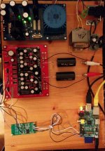
Currently the test setup is on a wooden board (see photo below), now it will be assembled into a case we purchased from ebay.

Today we did some first listening tests, and I can tell you, the result is awesome! The sound is very clear and crisp, locating the instruments etc. is great, it's like pulling a curtain away from the music.
We heard details in songs we never heard before, simply because the sound picture is so detailed that one can make out elements that were simply melted with other elements with the old DAC. It can be best described as "unblurring" a picture, similar when someone short-sighted puts his glasses on and can suddenly see a sharp picture and make out details he never knew they were there.
I have to add that the Hifi system we tested the DDDAC is nice but far from perfect, it consists of 20 years old Infinity speakers (approx. € 600 that time) and a common Denon amplifier. Nevertheless the difference was easy to make out and the DDDAC produced a sound not expected from this Hifi system.
So, all in all I want to thank everyone who contributed to this project, especially Doede, who came up with this design and also Enrico and others who gave me some helpful tips regarding the DDDAC and Raspberry!
Best Regards,
Hermann
Hi,
I just wanted to let you know that we (a group of friends in Austria/Vienna) just successfully finished our little DDDAC-Project. The setup is as follows:
- DDDAC Mainboard (red version)
- One DDDAC PCB
- DDDAC 12V power supply
- Mundorf Gold capacitors
- Raspberry Pi Vers. B as input source with Volumio
- DIYINHK isolator (for isolation of the I2S signal between Raspberry and DDDAC)
- Simple / non-switiching power supply for Raspberry
All in all the construction was relatively simple. The parts ordered from audiocreative - Audio Creative Shop DDDAC 1794 - WEB Shop Archives - Audio Creative Shop - arrived quite fast, sales was helpful in selecting the right parts. Soldering was quite easy too.
We selected better Mundorf capacitors (not too expensive) for output to improve quality a bit. Moreover, I was recommended to put an isolator between the Raspberry and the DDDAC, whereas the very cheap DIYINHK isolator seemed like a suitable solution and was not too hard to assemble.
After everything was soldered, we put all parts together - however, there was one problem: Audio was playing, but there was some hissing noise. When moving the I2S cables the hissing changed and eventually vanished. At that stage we used a cheap wallplug switching power supply for the Raspberry and thus exchanged it with a cheap non-switching variant - now the hissing is gone.
-> So it was interesting that the noise of the switching power supply did interfere with the I2S signal that much that it led to errors in the signal and thus to this hissing noise - I did not expect that.
Currently the test setup is on a wooden board (see photo below), now it will be assembled into a case we purchased from ebay.
Today we did some first listening tests, and I can tell you, the result is awesome! The sound is very clear and crisp, locating the instruments etc. is great, it's like pulling a curtain away from the music.
We heard details in songs we never heard before, simply because the sound picture is so detailed that one can make out elements that were simply melted with other elements with the old DAC. It can be best described as "unblurring" a picture, similar when someone short-sighted puts his glasses on and can suddenly see a sharp picture and make out details he never knew they were there.
I have to add that the Hifi system we tested the DDDAC is nice but far from perfect, it consists of 20 years old Infinity speakers (approx. € 600 that time) and a common Denon amplifier. Nevertheless the difference was easy to make out and the DDDAC produced a sound not expected from this Hifi system.
So, all in all I want to thank everyone who contributed to this project, especially Doede, who came up with this design and also Enrico and others who gave me some helpful tips regarding the DDDAC and Raspberry!
Best Regards,
Hermann
Attachments
Good work Hermann 🙂
Glad you are enjoying the creation and importantly, enjoying the music 🙂
I would suggest that you should try and keep your i2s wires as short as possible. Ideally less than 10cm.
Glad you are enjoying the creation and importantly, enjoying the music 🙂
I would suggest that you should try and keep your i2s wires as short as possible. Ideally less than 10cm.
cheers rax thats great
i suppose we would like to be able to vary the current a little, so option three would likely suit.
difficulty finding 1N5288 anyway
could you point us towards a schematic, bom please
thx again rax
Let me just add for now that the 2N4338 may be a good fit - Vgs(off) is less than 1V, which means no sorting by this parameter. Idss may be as low as 0.2mA, so it needs to be sorted out by this parameter, but this is the easy sorting.
Good work Hermann 🙂
Glad you are enjoying the creation and importantly, enjoying the music 🙂
I would suggest that you should try and keep your i2s wires as short as possible. Ideally less than 10cm.
Hi Hermann,
I am very glad to know that you can make the Rpi working... nice job indeed!
 and I quote 100% the message from James... the hissing noise that you describe is surely due to the too long length of the connection between the Rpi, the isolator and the DDDAC. And, if you have the chance, give a better power supply to the Rpi... he deserves it.
Regards,
Enrico
Nice to read this post. Very complete, good feedback and pictures 🙂
Fully agree on the loose wires... they can pick up garbage easily (also my experience)
Fully agree on the loose wires... they can pick up garbage easily (also my experience)
I wonder if smaller film caps be useful here? Must it be 47uf?
Many thanks,
Chanh
OK Guys, here is some answer ........ 😎
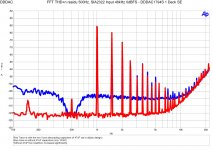
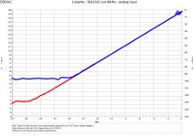
Did some testing on my single deck "test-dac" by measuring linearity and THD with noise floor with and without the 47uF and, yes you need the capacitors !!
Just look at the two measurements, explains it...
Did not do listening tests (as it is a bit work to do this on a 8-deck)
Something tells me, this position could be significant for SQ... (better quality 47uF, parallel film cap or something)
Attachments
Thanks Doede for this update!
Fortunately for me I haven't yet populate these caps and sounds like Jensen 47uf 150V will be replace the intended Elna Silmic 2 here! 🙂
Fortunately for me I haven't yet populate these caps and sounds like Jensen 47uf 150V will be replace the intended Elna Silmic 2 here! 🙂
After one night sleep this intrigues me. I want to be sure and would like to do some more checking... As said I build a one deck test dac with good open space (important to be tweaked capacitors 10mm above board and left a few out) so I can easily change with/without and swop between Tent Shunt and normal LDO situation. I built an exact "stock" copy to compare. I am less interested for this test case on final absolute sound, rather for comparison, so it will become clear where the real potential is for SQ tweaks. Now the Vcom capacitors can be part of that. Today is nice weather again, so I “have to” play golf first. 😀
Before listening, I will do some more measurements on the Vcom topic…
Before listening, I will do some more measurements on the Vcom topic…
- Home
- Source & Line
- Digital Line Level
- A NOS 192/24 DAC with the PCM1794 (and WaveIO USB input)