Hi Guys,
Well I got them populated but I'm too tired to try firing them up tonight. I wish I had known 1/4w was good I have plenty of those in 220R. I went ahead and installed the 270R 1/2W that I had. I had to stack some 2K 1/2W resistors for R113. Another resistor I forgot to order. Anyway, they're filled and I'm looking forward to firing them up in the morning. Not sure if I missed it, but what is the bias setting you are shooting for with these MOSFETs? Better yet, what mV across a .22R emitter resistor should I adjust to?
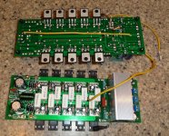
I tried taking some pics of the LED mounting but the heatsink kind of obscures it.
Blessings, Terry
Well I got them populated but I'm too tired to try firing them up tonight. I wish I had known 1/4w was good I have plenty of those in 220R. I went ahead and installed the 270R 1/2W that I had. I had to stack some 2K 1/2W resistors for R113. Another resistor I forgot to order. Anyway, they're filled and I'm looking forward to firing them up in the morning. Not sure if I missed it, but what is the bias setting you are shooting for with these MOSFETs? Better yet, what mV across a .22R emitter resistor should I adjust to?
I tried taking some pics of the LED mounting but the heatsink kind of obscures it.
Blessings, Terry
Attachments
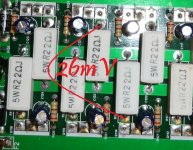
It shows distortion low enough even at 30mA per pair, so I run it at 60mA per pair now.
So even after running at high signal and suddenly appearing at low signal conditions, (there is a bias drop for some time before transistors cool down to "initial" temperature) - we are still in a safe area distortion-wise.
So even after running at high signal and suddenly appearing at low signal conditions, (there is a bias drop for some time before transistors cool down to "initial" temperature) - we are still in a safe area distortion-wise.
So please check my math. 60mA per pair is 26mv across an pair of .22R resistors?
Thanks, Terry
Thanks, Terry
Attachments
Last edited:
So please check my math. 60mA per pair is 26mv across an pair of .22R resistors?
Thanks, Terry
Exactly!
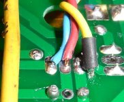
Is there any concern about the routing of the G2 ground wire? Will it have current induced into it if it runs parallel to the high current rails of the output stage? Is this a concern for the NFB wire as well?
Is there any concern about the routing of the G2 ground wire? Will it have current induced into it if it runs parallel to the high current rails of the output stage? Is this a concern for the NFB wire as well?
I pin my G2 wire down along the low current decoupling ground and drive traces. You could also fly the wire off the board closer the the heat sink. The best defence against induction is distance. That is also the reason for the NFB being flying wire.
Hi Guys,
Well I got them populated but I'm too tired to try firing them up tonight. I wish I had known 1/4w was good I have plenty of those in 220R. I went ahead and installed the 270R 1/2W that I had. I had to stack some 2K 1/2W resistors for R113. Another resistor I forgot to order. Anyway, they're filled and I'm looking forward to firing them up in the morning. Not sure if I missed it, but what is the bias setting you are shooting for with these MOSFETs? Better yet, what mV across a .22R emitter resistor should I adjust to?
I tried taking some pics of the LED mounting but the heatsink kind of obscures it.
Blessings, Terry
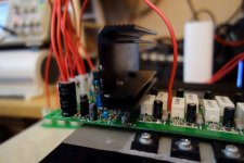
Yes, nice LED placement. I notice no hole in the heat sink to allow you to reach the bias adjuster though 😉.
Yes, I noticed that. I will have to drill a hole or flip the heatsink. I may just make a new heatsink that is flat. I don't like the fact that this one hides the cool little LED.
Terry,
I'm amazed at your ability to work through these projects. I barely have time to think about something and you all ready built it. Nice work.
What are you using for a power supply for the latest 5 pair set? I am thinking of a pair of these for a stereo amp. AN-6454 - 600VA 54V Transformer - AnTek Products Corp overkill....?Not big enough...?
Thanks, Evan
Initially, I will be using the same PSU I have been using for each of my Slewmaster builds, a 55V, 500va. If I like these MOSFETs they may go into the higher power amp I have planned. That will use the 65_0_65vac 800va transformer from my Super Leach.
That Antek looks like a good choice to me.
That Antek looks like a good choice to me.
Yes, I noticed that. I will have to drill a hole or flip the heatsink. I may just make a new heatsink that is flat. I don't like the fact that this one hides the cool little LED.
Yes, I think turning it around will solve the problem.
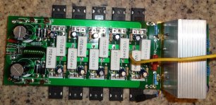
This is exactly the way my heatsink is arranged...
Attachments
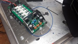
Mine turned out pretty well. These are going in a plate amp. I don't want the drivers to break off from the vibration.
This is a very solid design indeed!

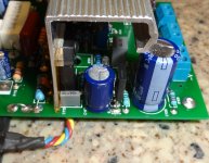
I flipped the heatsinks around. Easy-peesy. I have another issue however. I hooked it up this morning with my typical 18k resistors from VC+ to PD+ and VC- to ND-. With the pot turned all the way out, (full resistance) I get 21mV across a pair of resistors using the light bulb. Without the light I get 51mV. The pot will increase the bias so it is working properly. The other thing I notice is that I have about 3.5V at PD and -3.2V at ND RTG. I usually see about 1.9V there. I tried both boards and they are exactly the same. Any ideas? R107=680R, R113=550R, base stoppers=270R, VR106=200R
I'm attaching a pi of the front end for clarity.
I'm attaching a pi of the front end for clarity.
Attachments
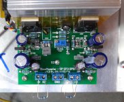
I flipped the heatsinks around. Easy-peesy. I have another issue however. I hooked it up this morning with my typical 18k resistors from VC+ to PD+ and VC- to ND-. With the pot turned all the way out, (full resistance) I get 21mV across a pair of resistors using the light bulb. Without the light I get 51mV. The pot will increase the bias so it is working properly. The other thing I notice is that I have about 3.5V at PD and -3.2V at ND RTG. I usually see about 1.9V there. I tried both boards and they are exactly the same. Any ideas? R107=680R, R113=550R, base stoppers=270R, VR106=200R
I'm attaching a pi of the front end for clarity.
Terry, I use 500R pot and it is somewhere in the middle. With 200R one you need to slightly increase R107 - 750R will be fine, I believe.
Higher PD and ND values are ok - this is because MOSFETS require higher bias voltage at the gates and this is why we had to modify the spreader (the main reason is different sensitivity, but higher voltage is also addressed)...
Last edited:
I kind of suspected that but before I started replacing things willy-nilly I thought Ihad better ask. I see that Jason changed R103 as well. I will try the higher value in R107 first.
Thanks, Terry
EDIT: I just noticed the little note to change the pot to 500R. I'll try the resistor change first.
Thanks, Terry
EDIT: I just noticed the little note to change the pot to 500R. I'll try the resistor change first.
Last edited:
I tried the 750R. Better but still too high. I'm out of 500R trimmers so I'll try going up in value on R107 to see if I can find a good fit. Try again after church.
Blessings, Terry
Blessings, Terry
- Home
- Amplifiers
- Solid State
- SlewMaster Builds