I read Bob Cordell's book that mosfet like run hot (high quiescent current). Lazy Cat set 200 mA drain current on VSSA.
Valery, can you set the quiescent current to 150 mA? I want to know if there is any audible difference. Thank you.
Hi Bimo, unfortunately we will have to wait until I switch to "production" heatsinks. The test ones I use at the moment appear too small (and thin) for real heat. Even with present 60 mA per pair they are rather hot (around 90C), so I'm sort of afraid to heat them up further...
Cheers,
Valery
P.S. My simulation shows the optimum quiescent current is around 90 mA, however I will definitely test up to 150 and measure distortion levels to see what the practical optimum is.
I thought I would just drill a small hole next to the emitter pad and feed the anode lead through that and solder to the emitter wire, and then solder the cathode directly into emitter pad. Should be easy. I like the idea of using an LED if it works.
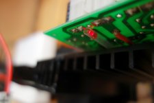
I have mounted the LED underneath the PCB but slightly away from the heatsink, using the full length of its pins and protecting them with a plastic pipe...
Running it together with my Low TIM hybrid now - beautiful

Attachments
Last edited:
Hi Bimo, unfortunately we will have to wait until I switch to "production" heatsinks. The test ones I use at the moment appear too small (and thin) for real heat. Even with present 60 mA per pair they are rather hot (around 90C), so I'm sort of afraid to heat them up further...
Cheers,
Valery
P.S. My simulation shows the optimum quiescent current is around 90 mA, however I will definitely test up to 150 and measure distortion levels to see what the practical optimum is.
I will wait. Thank you very much, Valery.
In an effort to learn something, is the purpose of the diode/LED to provide a voltage drop?
Thanks, Terry
Thanks, Terry
In an effort to learn something, is the purpose of the diode/LED to provide a voltage drop?
Thanks, Terry
Yes, as far as MOSFETs require higher bias voltage from the spreader, additional LED provides some additional voltage drop, at the same time decreasing the spreader's sensitivity (reducing over-compensation).
In an effort to learn something, is the purpose of the diode/LED to provide a voltage drop?
Thanks, Terry
Nope. The purpose of the LED or diode is to change the temperature coefficient of the VBE multiplier. That is to say we want to change how many mV of bias voltage reduction occurs for a given temperature rise. The reason for the diode being mounted separately is that we actually want it outside of the thermal loop we are trying to compensate. The root of this need is that we have output devices that have a different temperature coefficient and bias voltage requirements than we did with just BJTs.
Nope. The purpose of the LED or diode is to change the temperature coefficient of the VBE multiplier. That is to say we want to change how many mV of bias voltage reduction occurs for a given temperature rise. The reason for the diode being mounted separately is that we actually want it outside of the thermal loop we are trying to compensate. The root of this need is that we have output devices that have a different temperature coefficient and bias voltage requirements than we did with just BJTs.
Right, but we achieve this by adding an additional V drop outside of the thermal loop 😉
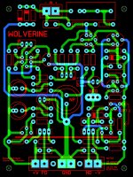
Wolverine nearing completion
Here is where Wolverine stands. Component designators still need to be applied.
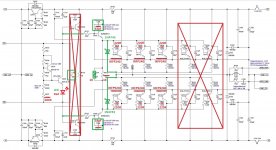
No one ever answered the query about Q10 on OS's Wolverine schematic. He had that as a TO-126 on the heat sink with Q11 and Q13 but I didn't think that was required since changing Q10's temperature will change the CCS current, but Q10 on its own dissipates almost nothing. I laid out using a TO-92 device for Q10. Anyone see an issue with that?
Here is where Wolverine stands. Component designators still need to be applied.
No one ever answered the query about Q10 on OS's Wolverine schematic. He had that as a TO-126 on the heat sink with Q11 and Q13 but I didn't think that was required since changing Q10's temperature will change the CCS current, but Q10 on its own dissipates almost nothing. I laid out using a TO-92 device for Q10. Anyone see an issue with that?
Attachments

Hmmmm, one says yes and the other nope. Yet, if I'm understanding this, the diode/LED is changing the temperature coefficient "by" lowering the voltage, correct? I guess what I'm trying to understand is whether the diode is being used to direct voltage or mainly to provide a voltage drop.
Thanks, Terry
Thanks, Terry
Right, but we achieve this by adding an additional V drop outside of the thermal loop 😉
I think we are expressing the same idea, just differently. The diode isn't there to provide added voltage drop. The standard VBE multiplier can be dialled up to any voltage we need. It is really there to modify the VBE's temperature coefficient and as a side effect it also gives us more voltage drop too.
In any event it seems to work nicely, be it an LED or a small signal diode. I haven't tried the LED but I trust it works fine with a change in the value of R107.
Yep 🙂
Here is where Wolverine stands. Component designators still need to be applied.
No one ever answered the query about Q10 on OS's Wolverine schematic. He had that as a TO-126 on the heat sink with Q11 and Q13 but I didn't think that was required since changing Q10's temperature will change the CCS current, but Q10 on its own dissipates almost nothing. I laid out using a TO-92 device for Q10. Anyone see an issue with that?
I didn't know if it was necessary either but since he went to the trouble of putting it there I bolted them to the heatsink. As a matter of fact since he placed Q12 next to the heatsink I assumed it needed to touch also so I put dab of glue on it and stuck it to the heatsink as well. I'm not sure if any of that was necessary but it plays fine.
Hmmmm, one says yes and the other nope. Yet, if I'm understanding this, the diode/LED is changing the temperature coefficient "by" lowering the voltage, correct? I guess what I'm trying to understand is whether the diode is being used to direct voltage or mainly to provide a voltage drop.
Thanks, Terry
Look at it this way. A transistors base-emitter voltage has a temperature coefficient of about -2.2mV/˚C, which means for every 1˚C the transistor increases in temperature it takes 2.2mV less voltage to forward bias the transistor junction.
Lets consider a simple VBE multiplier for illustration, rather than the compound one we are actually using (in simplistic terms, don't jump on me for lacking some technical details):
We use a VBE multiplier because we need to forward bias all the junctions in the OPS, for a total of six. So we set the VBE multiplier to multiply its base emitter voltage drop six times. This gives us the required voltage to forward bias the whole OPS of about 3.6V. This also multiplies the VBE multiplier's temperature coefficient by the same factor, so the temperature coefficient of the VBE multiplier becomes -13.2mV/˚C. If we are able to assume the transistors operate at the same temperature then the whole thing is stabilized against temperature changes.
Now consider the MOSFET option:
We are still using the VBE multiplier to provide the bias we need. We now have two BJT base-emitter junctions to forward bias and we have two gate-source bias voltages to supply. The total bias voltage we need to generate is on the order of ~8.4V (a little less that 'theory' would suggest). So we have to set our VBE multiplier up to provide something more like a multiplication factor of 14. the multiplier's temperature coefficient then becomes -30.8mV/˚C. However, the MOSFETs have a temperature coefficient of about -6mV/˚C, so the total temperature coefficient of the OPS is more like -16.4mV/˚C. This means we have a grossly overcompensated OPS. For every 1˚C rise in temperature the bias fall almost twice as much as it should to properly compensate. We need about half of the VBE multiplier to respond to temperature and the other half to not respond.
The solution:
When we insert the diode (or red LED) into the emitter leg of the VBE multiplier we are increasing the total voltage drop we are multiplying. More importantly only the transistor is thermally responsive, the diode is relatively isolated from temperature changes, so we get about half the regular VBE multiplier temperature coefficient. Happy days.
Thanks so much for the detailed explanation. I never really knew how the VBE multiplier worked aside from that it reduced the bias as it got hotter.
I'm going to go with the LED mounted on top and drilling the small hole to feed the one leg through. I like the idea of being able to see it and it will be better shielded from the heatsink.
Another question. Someone mentioned that the MOSFETs need to run at higher bias than the BJTs. Does this mean I will need a bigger heatsink for the MOSFET version?
Thanks, Terry
Thanks so much for the detailed explanation. I never really knew how the VBE multiplier worked aside from that it reduced the bias as it got hotter.
I'm going to go with the LED mounted on top and drilling the small hole to feed the one leg through. I like the idea of being able to see it and it will be better shielded from the heatsink.
Another question. Someone mentioned that the MOSFETs need to run at higher bias than the BJTs. Does this mean I will need a bigger heatsink for the MOSFET version?
Thanks, Terry
Hi Terry,
As I mentioned somewhere here, simulations show optimum quiescent current for IRFP240/9240 is around 90 mA, which is rather close to the one we use for BJT version. Moreover, MOSFETs may run a bit hotter in general, than BJTs, and that's ok for them, so I don't see the need for bigger heatsinks for the FETs.
Cheers,
Valery
I received my MOSFETs today. I sat down to start populating and realized I had not ordered anything for the base stoppers. So I have a couple of questions.
1) How important is it that the base stoppers are 1/2W? Do they see that much current?
2) How critical is the 220R value? I have 150R and 270R 1/2w in the bin, just no 220R.
Thanks, Terry
1) How important is it that the base stoppers are 1/2W? Do they see that much current?
2) How critical is the 220R value? I have 150R and 270R 1/2w in the bin, just no 220R.
Thanks, Terry
I would go for 270 ohm, but in reality almost anything from 100 ohm to 470 ohm will likely work. A slightly higher value will err on the side of caution.
- Home
- Amplifiers
- Solid State
- SlewMaster Builds