Xrk971, unfortunately the power smd are X5R ceramics. I started soldering them in directly to the positive trace leading to the +pins on the chip. When I had no room left I built upwards and back to the original place for the power caps. How high voltage do you think a 25V ceramic can handle over time? I'm running them now at 19V. They are all in parallell so 20x22uF on each side(40 total). Just 10 didn't do all that much but when I added 10 more and made the bridges, the amp suddenly came alive! The bridges are of course terminated at each end to effectively increase the thickness of the "wire"(+ trace). I just listened to my other tpa3116 which has a silmic 1000uf soldered directly to the pin and better brick(24V), and its sounds almost the same. Tomorrow I'll use the better brick to run the amp in the picture to compare at the same voltages.
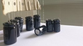
The heatsink is glued on the chip. Its made of copper sheets tinned together. The amp in the picture has film smds which I think sounds a bit more detailed than the upgraded ceramic bootstrap and input. I've also added snubbers to 2 of my cards and it really makes a difference🙂 There is something with the amp in the picture that makes the sound more realistic. The one in the picture uses 15uH and the other one uses 10uH. I'm not sure what sounds best at this point. I think I'm going to try 10uF toroids when they arrive in a couple of weeks.
The heatsink is glued on the chip. Its made of copper sheets tinned together. The amp in the picture has film smds which I think sounds a bit more detailed than the upgraded ceramic bootstrap and input. I've also added snubbers to 2 of my cards and it really makes a difference🙂 There is something with the amp in the picture that makes the sound more realistic. The one in the picture uses 15uH and the other one uses 10uH. I'm not sure what sounds best at this point. I think I'm going to try 10uF toroids when they arrive in a couple of weeks.
Depending on the brand of your ceramics the 22uF 'sticker value' could be anything between 4uF and 0.5uF once exposed to 19V. I'm not aware of any lifetime issues from running at 19V. I recommend TDK as having the best capacitance at bias characteristics.
Auch, I just took a look into ceramics and the ceramics I've used loose about 50% capacitance at 19-21V volts. So I should probably add a few extra^^. I've noticed that the ESR is about the same for aluminium electrolytics as for X5R ceramics. By my thinking having 20 X5R in parallell should give lower ESR than 1 oscon🙂
I'm very new to this and have gotten lost in all these pages of info. I just bought 2 of the green boards and was wanting to to use them both in PTBL mode tied together to have a 2 channel 100w per channel amp. The person I ordered to board from on Ebay said it was possible but after reading here for hours it seems like it's not really going to benefit me any. Can someone help me to understand this? I also need help in deciding on what power supply to run these two boards if biamping is possible. Hopefully I didn't just spend extra money for no reason. Thanks
I'm very new to this and have gotten lost in all these pages of info. I just bought 2 of the green boards and was wanting to to use them both in PTBL mode tied together to have a 2 channel 100w per channel amp. The person I ordered to board from on Ebay said it was possible but after reading here for hours it seems like it's not really going to benefit me any. Can someone help me to understand this? I also need help in deciding on what power supply to run these two boards if biamping is possible. Hopefully I didn't just spend extra money for no reason. Thanks
Most boards come stock in BTL mode, which for practical purposes means two channel i.e. stereo.
PBTL mode, on the other hand, is one channel/mono, and does double the effective potential output---but only at the lowest impedance which happens to be 1.6 ohms.
The BTL/stereo mode will work with loads as low as 3.2 ohms. If your speakers don't go below that (most don't), then indeed, you will not see any benefit in terms of output power by running your board in PBTL mode.
There may be some sonic (i.e. sound quality) benefits to running like this. I haven't tried it, and I don't recall it ever being discussed in this thread (though my memory isn't the greatest).
You can run two boards on one power supply, though it's recommended to configure one as master and the other as slave. This has been discussed a few times in this thread, but unfortunately, I don't have a link handy.
As for what power supply... your options are numerous. Many are using cheap 19V laptop/monitor power supplies. Meanwell is a brand that has a good reputation for good quality SMPS. A lot of attention has been given to HAM radio power supplies made by Astron (typically 13.8V, but they also make 28V linear supplies, e.g. LS10A, adjustable from 22--32V).
I'm planning on using this with my 6 ohm Pioneer 22's so I guess there is no benefit to running both amps? I was hoping for higher wattage for the days when no one is home and I really crank up the volume. I might just run one of the amps and put some money into a nice preamp and use the second amp for another system. I wish the ebay seller would have been upfront about this when I questioned him about it. Thanks for the reply.
Auch, I just took a look into ceramics and the ceramics I've used loose about 50% capacitance at 19-21V volts.
To only lose 50% with 80% bias for a 22uF ceramic would be a bit of a miracle. What case size and brand are they?
So I should probably add a few extra^^. I've noticed that the ESR is about the same for aluminium electrolytics as for X5R ceramics.
On datasheets I've looked at, ceramics generally beat electrolytics for ESR. Normally ceramics have ESRs in the single digit millohms but at higher frequencies than 'lytics due to their smaller values.
By my thinking having 20 X5R in parallell should give lower ESR than 1 oscon🙂
Absolutely and by a not small margin either. Probably cheaper overall too provided you buy the ceramics in large quantities (a reel at a time).
I used X5R 1210 package and from this link I got the estimates; Temperature and Voltage Variation of Ceramic Capacitors, or Why Your 4.7F Capacitor Becomes a 0.33F Capacitor - Tutorial - Maxim
Looks like TDK doesn't make an X5R 22uF/25V in 1210 but Murata does. If you scroll down here - Capacitors | details for GRM32ER61E226KE15# | Murata
you'll see you get only 30% of the original capacitance at 19V.
you'll see you get only 30% of the original capacitance at 19V.
Anyone seen this TPA3116D2 version?
Another board version seems to be available.
Anybody have any experience with it?
It is paired with a preamp, digital display, tone controls, switched inputs, 30dB gain.
High-power digital amplifier board TPA3116D2 + PT2313 remote control 50W +50 W
Joe L.
Another board version seems to be available.
Anybody have any experience with it?
It is paired with a preamp, digital display, tone controls, switched inputs, 30dB gain.
High-power digital amplifier board TPA3116D2 + PT2313 remote control 50W +50 W
Joe L.
On datasheets I've looked at, ceramics generally beat electrolytics for ESR. Normally ceramics have ESRs in the single digit millohms but at higher frequencies than 'lytics due to their smaller values.
Are you sure this is true with the OSCON's ? I think the Panasonic SEPF 330uF 25v states that ESR is 11mOhm. That is pretty low and it is designed to be operated at bias.
Yes, ceramics have lower ESR even than OSCONS - for example a 10uF/25V 1206 drops below 10mohm ESR at 20kHz. Oscons of course have higher capacitance - low ESR isn't everything.
Are you sure this is true with the OSCON's ? I think the Panasonic SEPF 330uF 25v states that ESR is 11mOhm. That is pretty low and it is designed to be operated at bias.
There are wet electrolytics with lower ESR then solid Oscons too.
Another board version seems to be available.
Anybody have any experience with it?
It is paired with a preamp, digital display, tone controls, switched inputs, 30dB gain.
High-power digital amplifier board TPA3116D2 + PT2313 remote control 50W +50 W
Joe L.
Some have this version for some time, yes. I feel input capacitors could be better film then electrolytics. Remote works without anything added to the audiosignal, switching without any beep/click/pop/noise, including on/off, meaning I hear pop on/off with "audiobah" but I don't hear any pop or any other noise with this board.
Quality low level detail in dynamic recordings superior to all other 3116 available on Ebay except hiampmini.
Oh almost forgot, replacing the fake Rubycons on the Wiener and lowering gain from 26 to 20dB improves SQ. And Wiener wasn't bad originally 🙂 No time to compare directly.
Attachments
Last edited:
Perhaps I'll try adding oscons too but it doesn't sound like 30% capacitance. I use a power brick and the voltage is always super stable. I haven't got the equipment to measure ripple so there there could be a lot to gain still🙂 I use film smds which I think sounds really good! Especially film smd in the bootstrap position. The film have uber short soldering plates with a lot of area, on paper they have lower esr than ceramics and they are super voltage stable. They only go a few millimeters above the ground layer so I don't think they radiate emr as much as standing films.
Oh almost forgot, replacing the fake Rubycons on the Wiener and lowering gain from 26 to 20dB improves SQ. And Wiener wasn't bad originally 🙂 No time to compare directly.
Did you replace the 20 kohm surface mount gain setting resistor with a similarly-sized 5.6 kohm to lower the gain?
I want to do the same with my Ybdz/Wiener board, but those stock resistors are tiny... not sure if my soldering skills are up to it.
Did you replace the 20 kohm surface mount gain setting resistor with a similarly-sized 5.6 kohm to lower the gain?
I want to do the same with my Ybdz/Wiener board, but those stock resistors are tiny... not sure if my soldering skills are up to it.
I removed the 100K resistor, nearest of two to chip, they are parallel to chip. They indeed are very small 😀 Fortunately no need to replace the 30C/20k resistor 😀
Perhaps I'll try adding oscons too but it doesn't sound like 30% capacitance. I use a power brick and the voltage is always super stable. I haven't got the equipment to measure ripple so there there could be a lot to gain still🙂 I use film smds which I think sounds really good! Especially film smd in the bootstrap position. The film have uber short soldering plates with a lot of area, on paper they have lower esr than ceramics and they are super voltage stable. They only go a few millimeters above the ground layer so I don't think they radiate emr as much as standing films.
I and quite a few others have found the Panasonic SEPF OSCON caps to work very well with the TPA3116. Per the datasheet, the 330uF/25 SEPF OSCON has an ESR of 14 mOhms (100kHz to 300kHz at 20 degrees C).
http://industrial.panasonic.com/ww/i_e/00000/id_oscon1309_e/id_oscon1309_e.pdf
These are not the panacea for DC decoupling, but my listening experience tells me that they work well with the TI TPA31xx amps, they are easy to obtain, and they are not expensive.
That's what I did with the 3116... I replaced the ones closest to the chip. On the 3110, the odd pair towards the center may have the shortest path to the chip. I'll have to check.
I did the Oscon cap swap on my new 2x15 3110 Sure board that you suggested
 I really like this board, even more now! Thanks....
- Home
- Amplifiers
- Class D
- TPA3116D2 Amp