This is a simulation, but that amp was built and is working with no problem ever sins.
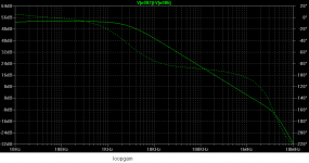
It is my TT amp, presented here in one thread. The loop gain at 20 kHz is 67 dB. It is two pole compensation and it shows that with correct simulation.
Putting the compensation issue aside for a moment, the reason for your EF-transistor blowing problem is right there on the schematic. You have connected the collector of the current limiting transistor to the emitter of the EF, and not its base, as you should have done.
Result- limiter operates, EF is connected directly between rail and ground... Bang.
When I see simulated bode plots it gives me a chuckle, only because it's never translated into the actual working circuit well at all. Once physical traces are introduced the simulation is moot.
Colin
Colin
Result- limiter operates, EF is connected directly between rail and ground... Bang.
Exactly.
Putting the compensation issue aside for a moment, the reason for your EF-transistor blowing problem is right there on the schematic. You have connected the collector of the current limiting transistor to the emitter of the EF, and not its base, as you should have done.
Result- limiter operates, EF is connected directly between rail and ground... Bang.
That is my TT amp you are talking about, there is protection resistor between EF collector and the ground and that EF never blew. It was my first blameless that blew.
I simulated exactly your connection of the current limiting transistor and that simulation shows that EF transistor is going to blow before the current limiter even start to limit. That shows that is not important where the current limiting transistor is connected, without that resistor EF will blow at heavy overload.
ps. In my opinion there is no need for VAS current limiting transistor, but EF protection resistor is enough. The current limiting is needed for simple VAS with no EF enhancement.
Last edited:
When I see simulated bode plots it gives me a chuckle, only because it's never translated into the actual working circuit well at all. Once physical traces are introduced the simulation is moot.
Colin
illustrating principles is a fine use for sim - may be simplified or gussied up to what ever degree is appropriate
sim often is more "realistic" than the equations we can manage to write, manipulate and "follow" mentally
I agree that few outside the switching power supply industry actually even attempt loop gain measurement with injected signals
http://www.newtons4th.com/wp-content/uploads/2010/03/TestingLoopStabilityv2.pdf
http://www.google.com/url?sa=t&rct=...OV0PqXf4mLv8U5cqA&sig2=dZ_XeFlPCVo6Dxqz7oHTvw
but it turns out that these principles most easily viewed in Bode plots actually help designing stable real world feedback controllers
for a few generations of engineers by now
Last edited:
When I see simulated bode plots it gives me a chuckle, only because it's never translated into the actual working circuit well at all. Once physical traces are introduced the simulation is moot.
Chuckling is good for you. However, those pesky non-chuckling engineers that are designing automation equipment (and not only electric) are successfully using those plots for over 50 years. We landed on the moon using those, you know.
sim often is more "realistic" than the equations we can manage to write, manipulate and "follow" mentally
On this one, I strongly disagree. Simulations are a necessary evil (once that a certain level of circuit complexity was reached), but usually fail short of providing the deep understanding that pen and paper always is.
I didn't claim anything about which promotes deeper understanding, did I?
only that sim can be done at various levels of complexity to suit what you are investigating - from ideal gm, I,V source blocks, Laplace Behavioral sources, that are just visual block diagram implementations of simple equations to some useful levels of device and parasitic modeling
some may find the block diagram, "wired equations", stepped parameter analysis with waveform probes and plots approach fits their thinking style
and I do claim the sim approach does call on skills we need for real circuit design and debugging such as reading, reasoning from schematics to probing, looking at waveforms, conceiving, interpreting "tests" based on observing, injecting signals, changing components or topology
Last edited:
How about this loopgain plot (stable enough, in a real world).
Pavel, I suppose you used ltspice. Please try this:
Place another voltage source between out and the feedback network, - to out and + to feedback. Label the nets 'out' and 'fb', respectively. Set the voltage to 0 and AC to 1. Set the input voltage source to AC 0. Run the sim and plot '-V(out)/V(fb)'. Post the result here 🙂
I think you use Middlebrook method. Why do not use Tian Probe?
To measure loop gain you can use ltspice_instalation_folder\LTspiceIV\examples\Educational\loopgain.asc and ltspice_instalation_folder\LTspiceIV\examples\Educational\loopgain2.asc
ltspice_instalation_folder is folder instalation of ltspice, something like "C:\Program Files (x86)\LTC"
The loopgain simulation was done almost the same way that Preamp has described. For a comparison with real world, I measure open loop gain and closed loop gain and make a subtraction.
I think you use Middlebrook method. Why do not use Tian Probe?
my reason for using the "less accurate", single test source is because Tain/dual injection is a pain due to the complicated equation involving stepped traces which makes it very difficult to move, copy, duplicate in a side-by side comparison
effectively prohibits stepping any other parameter in the sim
when the single Vsource injection conditions for adequate loop gain measurement accuracy are met it is much simpler and more flexible in application
Last edited:
That's not saturation, saturation is at Vce=0. If you tie the base to the collector in an EF, then Ic=(Vcc-Vbe)/Re and Vce=Vcc-Ic*Re= Vbe. Of course, if Vcc>>Vbe, then Ic->Vcc/Re and Vce->0, but is never zero, hence the EF never saturates.
Hmmm. I understand saturation as the state where additional base current does not increase the collector current any further. Is that not the case for an EF, or am I wrong?
Jan
my reason for using the "less accurate", single test source is because Tain/dual injection is a pain due to the complicated equation involving stepped traces which makes it very difficult to move, copy, duplicate in a side-by side comparison
effectively prohibits stepping any other parameter in the sim
when the single Vsource injection conditions for adequate loop gain measurement accuracy are met it is much simpler and more flexible in application
Yes, this method is accurate enough for the VFA amp simulation, but not for the CFA amp where FB current is quite higher.
The loopgain simulation
This is another circuit, by Middlebrook method. And another one.
Attachments

Last edited:
my reason for using the "less accurate", single test source is because Tain/dual injection is a pain due to the complicated equation involving stepped traces which makes it very difficult to move, copy, duplicate in a side-by side comparison
effectively prohibits stepping any other parameter in the sim
when the single Vsource injection conditions for adequate loop gain measurement accuracy are met it is much simpler and more flexible in application
Thank you, jcx. It confirm my experience, too.
Is it enough "accurate" to use Middlebrook method (assuming we make good layout)?
The loopgain simulation was done almost the same way that Preamp has described. For a comparison with real world, I measure open loop gain and closed loop gain and make a subtraction.
Can you describe how did you measure open loop gain and closed loop gain?
Closed loop gain is an amplifier gain with feedback closed.
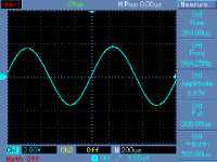
I measure open loop gain with feedback open. Some topologies with DC servo make it possible. In this case, it was an amplifier similar to a "generic amplifier", with no DC servo, with capacitor from lower FB resistor to ground - and - this is a necessary condition - input differential pair carefully balanced. Then you get acceptable DC output offset. Attached is an open loop output voltage, OLG = 80.8dB. Just do it for different frequencies.
I measure open loop gain with feedback open. Some topologies with DC servo make it possible. In this case, it was an amplifier similar to a "generic amplifier", with no DC servo, with capacitor from lower FB resistor to ground - and - this is a necessary condition - input differential pair carefully balanced. Then you get acceptable DC output offset. Attached is an open loop output voltage, OLG = 80.8dB. Just do it for different frequencies.
Attachments
Hmmm. I understand saturation as the state where additional base current does not increase the collector current any further. Is that not the case for an EF, or am I wrong?
The saturation region of operation is characterized by forward bias potentials on both the base-emitter and base collector junctions (implying
VBE ≥ VCE).
The EF is at most at "incipient saturation", with VBE=VCE and VCB=0.
I measure open loop gain and closed loop gain and make a subtraction.
With all due respect, I don't believe you. That would work only for very modest open loop gains (and don't ask me how I know). Determining the loop gain from the open loop gain and the closed loop gain is otherwise extremely sensitive to experimental and numerical errors. Please show your complete results and methodology, a sine on a scope screen doesn't say anything relevant.
Building a probe to measure directly the loop gain is very easy, but of course it then requires a log sweep generator from KHz up to 5-10MHz.
- Status
- Not open for further replies.
- Home
- Amplifiers
- Solid State
- Your opinions are sought on Audio Power Amplifier Design: 6th Edition. Douglas Self