That's where I end up.
I don't know why that's happening, correct page is #207.
Hi,
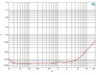
Real world THD+N measurement on a symetrical design with mosfet output.
100W and 30W 8Ohm BW=80kHz
100W first then 30W
\\\Jens
Real world THD+N measurement on a symetrical design with mosfet output.
100W and 30W 8Ohm BW=80kHz
100W first then 30W
\\\Jens
Attachments

Last edited:
I don't know why that's happening, correct page is #207.
Page numbers depend on how many "threads per page" you have your forum user settings configured for.
If you get weird results or pages or threads don't display then clear your browser cache of all history and also delete all temp files (a disk clean)
Page numbers depend on how many "threads per page" you have your forum user settings configured for.
If you get weird results or pages or threads don't display then clear your browser cache of all history and also delete all temp files (a disk clean)
I don't think is only that. Why still4given vent to correct page, and for me it shows correct page?
I guess that Rotel RB1090 is almost identical.
No. The RB-1090 has a cascoded input stage, and a cascoded VAS, the RB-1080 does not. I don't call that identical.
Like I said, elektrotanya.com has the RB-1080 service manual.
I would, really like to have your comment on this here http://www.diyaudio.com/forums/soli...-6th-edition-douglas-self-21.html#post4011827. If you think it's not worth to be implemented, please, explain why.
BR Damir
I have never yet had any troubles with the EF transistor blowing if the main VAS transistor is current-limited in the usual way. What would make it blow if it is only turned on enough to allow, say, 20 mA, through the main VAS transistor?
I don't see the failure mechanism.
The link takes me straight to #207.
Hi,
Real world THD+N measurement on a symetrical design with mosfet output.
100W and 30W 8Ohm BW=80kHz
100W first then 30W
\\\Jens
From the relatively low THD levels, I assume there are EF's applied to the VAS's?
Can you show us the schematic?
From the relatively low THD levels, I assume there are EF's applied to the VAS's?
Can you show us the schematic?
Yes, the VAS is buffered, and no - I cannot share the schematics - sorry ...
It's fairly standard stuff:
Input is cascoded BJT - interface to VAS is not seen often - no current mirrors
VAS is cascoded and buffered to isolate the non linear loading output stage.
Output stage for the plots are Source followers
Components are all SMT except for output devices
Circuit is not at all optimized regarding loop (Purely done on the simulator) and DC currents in the different stages, i expect to lower THD by a factor of 2-3 at higher frequencies by doing this.
Best regards
Jens
Last edited:
It is interesting to note that what you call class S, the RF world calls a Doherty amplifier,
I didn't call it Class-S, Sandman did.
I often find that (In the sound reinforcement game) an amp thermally limited to maybe a couple of hunded watts but with sufficient voltage and SOA headroom to deliver an extra 10dB at a 5% duty cycle is a MUCH more useful animal then a amp rated for double the power but which runs out of voltage swing at that power.
This a prehaps a good argument for class G or some form of envelope tracking power supply.
Regards, Dan.
+10 dB is ten times the power. Isn't that asking rather a lot?
I suppose Class-G might be able to do it.
Yes, the VAS is buffered, and no - I cannot share the schematics yet... we (B&O) have just filed for a patent for the circuit related to BIAS setting.
The rest is fairly standard stuff:
Input is cascoded BJT - interface to VAS is not seen often - no current mirrors
VAS is cascoded and buffered
Output stage for the plots are Source followers
Best regards
Jens
I meant, is there an EF inside the VAS Miller loop?
I wasn't thinking of buffering the VAS output.
I meant, is there an EF inside the VAS Miller loop?
I wasn't thinking of buffering the VAS output.
Hi,
Sorry missed that - no, but compensation is multi poled.
\\\Jens
Hi,
Real world THD+N measurement on a symetrical design with mosfet output.
100W and 30W 8Ohm BW=80kHz
100W first then 30W
\\\Jens
A little too much THD at 20khz. Can u showing us the open-loop bode plot ?
A little too much THD at 20khz. Can u showing us the open-loop bode plot ?
I don't have real data - only simulated - but time domain has been stable until now.
Gain reserve in the simulator is about 42dB at 20kHz and phase margin > 50 degrees - this was done so I did not have to deal with destructive oscillations.
I need to build a second prototype and optimize the open loop response before I will go into details on loop.
The rest of the circuit is still early days - I just posted in relation to discussion about balanced topologies.
Best regards
Jens
I have never yet had any troubles with the EF transistor blowing if the main VAS transistor is current-limited in the usual way. What would make it blow if it is only turned on enough to allow, say, 20 mA, through the main VAS transistor?
I don't see the failure mechanism.
The link takes me straight to #207.
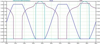
Simulation shows (did you take look to the simulation attached?) that VAS current limiter does not start to limit and EF transistor goes up over 2 W of dissipation. Did you tray to simulate it, no need to blow real transistor? When I made my first blameless after your article series of power amp distortions in WW, it blew the EF transistor (there was not VAS current-limited yet, but I think that it could not save it) after some hard clipping transients, and then I included that protection resistor and it never happened again even with no current limiter.
By the way with your 10R resistor in the VAS emitter, current limit is set a bit over 60 mA.
I attached again the simulation plot, with output voltage, EF transistor (Q7) current and VAS (Q9) current.
BR Damir
Attachments
Everybody knows that.
Apparently not.
Any other examples, dated after I was born?
When were you born?
Best wishes
David
FWIW, 1988
When you were 6 years, ICEpowers founder Karsten worked on his Phd... I was an apprentice back then (Still is for that matter) I guess the main point of technical and commercial focus since has been switched amplifier technology.
\\\Jens
Simulation shows (did you take look to the simulation attached?) that VAS current limiter does not start to limit and EF transistor goes up over 2 W of dissipation.
Something wrong with your simulation, I think.
When I made my first blameless after your article series of power amp distortions in WW, it blew the EF transistor (there was not VAS current-limited yet, but I think that it could not save it)
Well, surely there's your problem. No current-limiting.
- Status
- Not open for further replies.
- Home
- Amplifiers
- Solid State
- Your opinions are sought on Audio Power Amplifier Design: 6th Edition. Douglas Self