@SyncTronX -- you can't tune or use the notch filter successfully in FR mode, you have to use the Spectrum Analyzer -- in FR mode, the signal is not fine enough in frequency steps and doesn't stay in place long enough at the significant frequencies to give the needed resolution. So just use the SA mode for tuning your notch. Many people who have seen my webpage on the T-T filter have made this mistake and I've answered a pile of emails about it.
Your version of the T-T with 3 equal value caps may have higher insertion loss than the one with C and 2C -- R and 1/2R config. I've never run the difference in LTSpice to see if it matters.
Your version of the T-T with 3 equal value caps may have higher insertion loss than the one with C and 2C -- R and 1/2R config. I've never run the difference in LTSpice to see if it matters.
The FR is just to look at the symmetry to see if something is wrong.
It looks like something is wrong.
The three equal cap version can get you a high or low pass response TT. WJ covers this in his book and there is a Bell labs paper floating around that gets into in more detail.
I think you should try Dick suggestion, It's works.
It looks like something is wrong.
The three equal cap version can get you a high or low pass response TT. WJ covers this in his book and there is a Bell labs paper floating around that gets into in more detail.
I think you should try Dick suggestion, It's works.
I'll try and look it up on Richiems web pages.
Breathing room and lettng frustration go.
I'll try again later.
Breathing room and lettng frustration go.
I'll try again later.
The Panasonic polypropylene work wonders for me. When I tested them for matching on an ESI bridge I got an exact null per pair of three sets. Not bad.
David,
Do you know which Panasonic poly's you used?
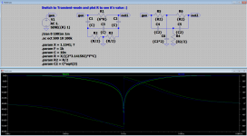
Just checked some notch models and made a .asc file for it, for any one interested here it is. The 'X'-factor is 1.1541, can any one tell me what it is 🙂
P.s. The text should read 'Switch to Transient-mode and plot gen, out1 or out2 to see the value of R (sorry for that)
P.s. The text should read 'Switch to Transient-mode and plot gen, out1 or out2 to see the value of R (sorry for that)
Attachments
David,
Do you know which Panasonic poly's you used?
Of course. I'll post it later today.
Thanks David!
ECW-F4684HL PP Metalized Panasonic
ECW-H12682JV PP Metalized Panasonic
ECW-F6683HL PP Metalized Panasonic
these are the ones used in mu oscillator. I don't remember the values in the TT.
This points you to the series.
In Stock at Digi.
Don't be concerned with Panasonic's application category. They're the same cap.
Thanks David.
SyncTronX, here are some screen shots I gathered tonight to help you. Hopefully this make sense.
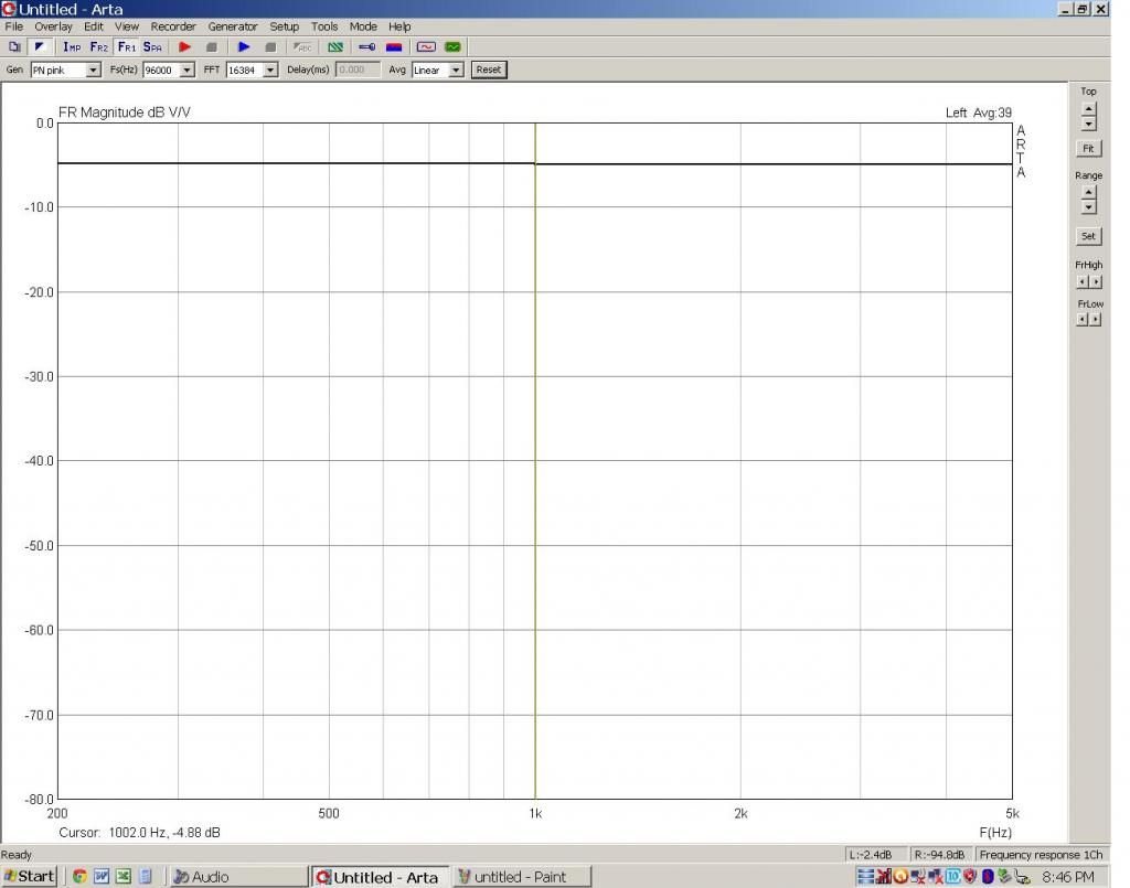
Reference ( I used - 5dB so you could see the line easily)
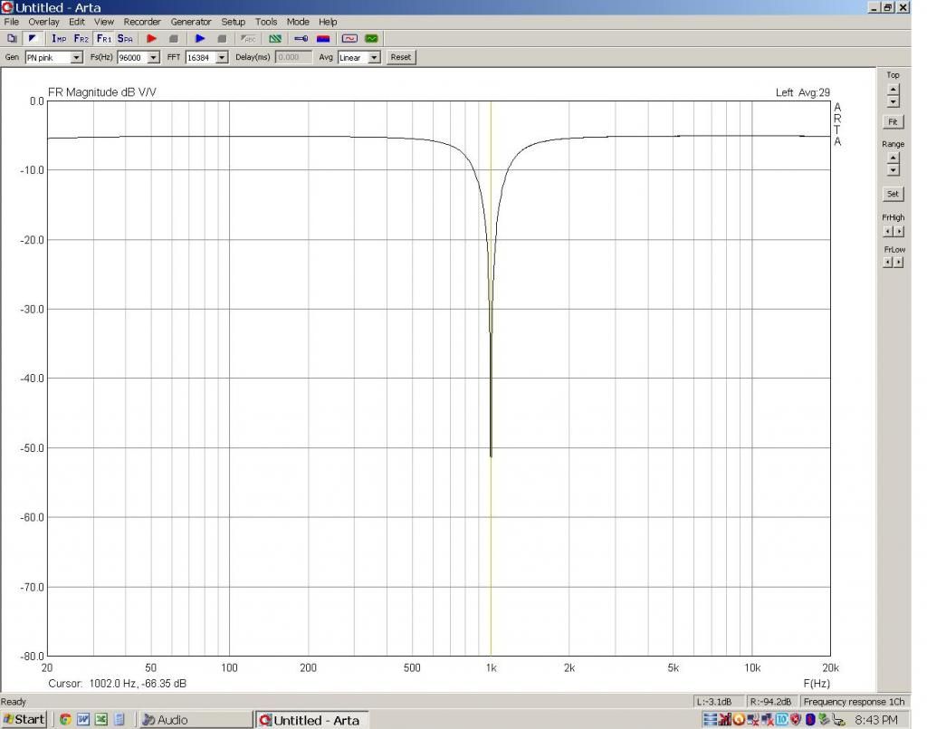
Notch at -60dB (-65dB since we are starting at -5dB)
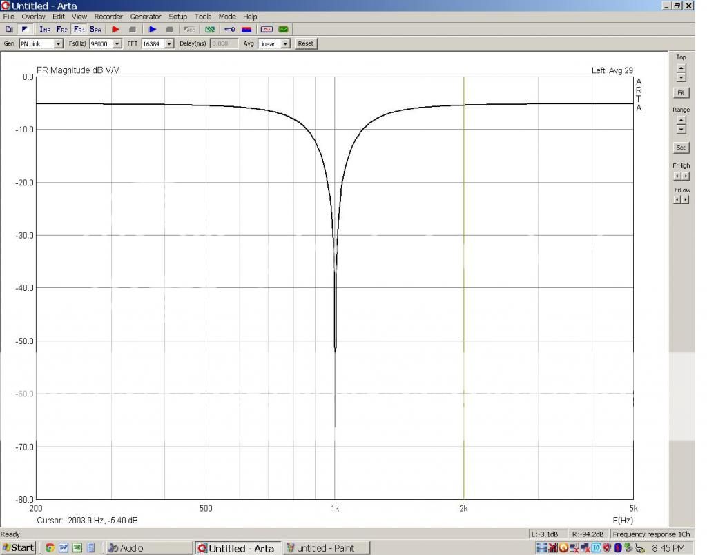
Notch frequency response from 200Hz to 5KHz
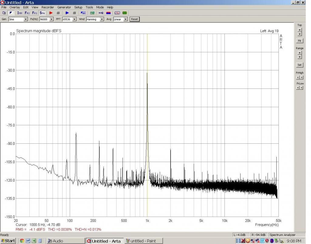
My bench amp at 15 Watts
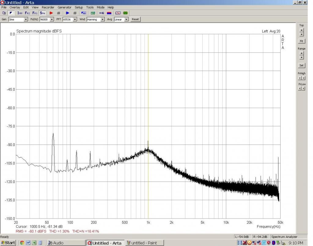
Bench amp at 15 Watts with Notch active (-60dB)
It has taken me a long to get to this point, keep going!
Skidave, trying to understand the last graph?
I would have expected to see MORE 2nd, 3rd, etc. harmonics, given that the fundamental is/was notched out?
Unless the harmonics present are artifacts of the soundcard?
The 60Hz. seems the same.
So, at least I don't know what I am seeing.
I would have expected to see MORE 2nd, 3rd, etc. harmonics, given that the fundamental is/was notched out?
Unless the harmonics present are artifacts of the soundcard?
The 60Hz. seems the same.
So, at least I don't know what I am seeing.
@bear -- removing more of the fundamental lowers the distortion caused by the fundamental in the ADC box, so the residuals are lower. Ultimately, of course, limited by the noise floor.
Ok, so as I mentioned, effectively lowers the residuals of the soundcard... fine, now where is the distortion from this "bench amp"?? 😀
Let's see this amp! 😀
What is the effective distortion level represented by the reading shown at 1kHz in that graph? Same as before, only with lowered soundcard residuals?
Following in the libretto...
_-_-
Let's see this amp! 😀
What is the effective distortion level represented by the reading shown at 1kHz in that graph? Same as before, only with lowered soundcard residuals?
Following in the libretto...
_-_-
@bear -- I should have looked more closely -- didn't know that was the bench amp; I'm guessing the notch is in front (!) of the amp, not after it....
I think the gain scaling is off on the second graph. The 60 Hz "marker" (hum) should be adjusted to the same level to compare the graphs. There seems to be a lot of insertion loss through the notch as configured.
Skidave,
Thanks for taking the time to post the ARTA screens for me.
Bear,
How do I find out what the Bin frequencies are that they QA400 prefers?
Thanks for taking the time to post the ARTA screens for me.
Bear,
How do I find out what the Bin frequencies are that they QA400 prefers?
Sync, your welcome.
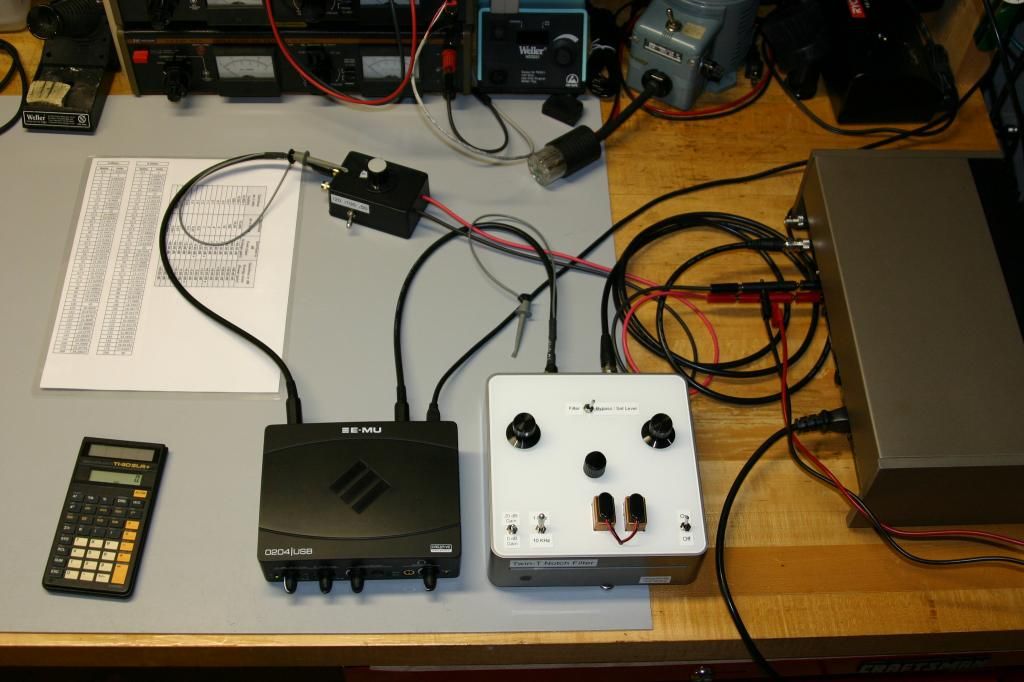
Bear, Demian and Dick, the 'bench' amp is an older Quad 405-2. It has not been modded but could use a power supply cap replacement. I feel it is good for a bench test amp with gear.
Yes, the notch is in front of the amp. Here is the setup: EMU-0204 out - Notch - Amp- Voltage Divider - back into EMU.
Demian, there is no loss from the notch that I can measure (outside the notch area). The two screen shots are from the notch in bypass and then the notch active.
Can you scale ARTA? I did not see that?
I do agree the 60Hz noise picks up with the notch. I threw this all together quickly the other night and did not do a good job with signal cable management. See photo below.
This is all great discussion and I'm happy to be involved and better up to speed than before.
Sync, one last thing. In my photo you will see a laminated sheet with some numbers. I made this to help with quick math. Two columns are voltage out converted to Watts and then the other is a bunch of distortion % to dB and scale factors.
Dave
Bear, Demian and Dick, the 'bench' amp is an older Quad 405-2. It has not been modded but could use a power supply cap replacement. I feel it is good for a bench test amp with gear.
Yes, the notch is in front of the amp. Here is the setup: EMU-0204 out - Notch - Amp- Voltage Divider - back into EMU.
Demian, there is no loss from the notch that I can measure (outside the notch area). The two screen shots are from the notch in bypass and then the notch active.
Can you scale ARTA? I did not see that?
I do agree the 60Hz noise picks up with the notch. I threw this all together quickly the other night and did not do a good job with signal cable management. See photo below.

This is all great discussion and I'm happy to be involved and better up to speed than before.
Sync, one last thing. In my photo you will see a laminated sheet with some numbers. I made this to help with quick math. Two columns are voltage out converted to Watts and then the other is a bunch of distortion % to dB and scale factors.
Dave
Ummm... the notch needs to be *after* the amp, so that the only thing going to the distortion analyzer *is* the distortion! If you don't put the fundamental into the amp, it won't make any distortion! 😀
Thought you might have found a Roswell amplifier...
_-_-
PS. ur bench is too clean.
Thought you might have found a Roswell amplifier...
_-_-
PS. ur bench is too clean.
Last edited:
oh yeah, how to find the freqs?
not sure if the QA reads them out or not. that would be the first thing to look at. (don't recall, haven't fired mine up in quite a while now...)
Second way is to put a good freq counter on the output of the QA.
Thurd way is to move ur freq gen around the nominal freq and look real-time at the shape of the fundamental shown on the QA, when ur "in bin" that shape looks very tight and has no big skirt on the bottom. Best that your oscillator be stable and easy to adjust in "vernier" steps.
I noticed this when I used the VP-7725 as the external oscillator, had to dork it down to several decimal places to get it into the "bin". Lucky that this unit does that trick. An analog oscillator would be more difficult I expect.
Here a question for the FFT gurus.
FFT assumes a periodic continuous wave form. This implies a frequency centered of the bins.
Sine will satisfy this condition. Will cosine also satisfy this condition or does FFT require beginning and ending at the zero crossing?
FFT assumes a periodic continuous wave form. This implies a frequency centered of the bins.
Sine will satisfy this condition. Will cosine also satisfy this condition or does FFT require beginning and ending at the zero crossing?
Its all about the windowing. if everything is synchronous and starts and stops at a zero crossing you can use no window. In reality you do need windowing. How the window deals with the beginning and end of the sample has a lot to do with the information in the translation. Clean waves can be processed with different windows or no window if the start and stop are on the mark. If you are looking and a mix of stuff then windowing is critical and different window functions can highlight different aspects of the signals.
In the real world neither the source nor the sampling system are free of jitter or drift so everything will move inside the bins. In the high resolution measurements I'm making a small amount of drift during the measurement can completely remove a signal.
In the real world neither the source nor the sampling system are free of jitter or drift so everything will move inside the bins. In the high resolution measurements I'm making a small amount of drift during the measurement can completely remove a signal.
- Home
- Design & Build
- Equipment & Tools
- QuantAsylum QA400 and QA401