Personaly made measuring station for fast calibration and test procedure. 🙂You personally calibrated the fabrication machinery for the PCB and SMT production?
LOL
THE POWER OF INSIDER DIY!
First cases will be received by GB members soon. Their comments will be most relevant, stay tuned.WOW
That's a nice chassis! I was thinking your chassis would be some rolled case fabricator order online!
hahaha
WOW
It's not cheap but it's also not expensive considering it's tier one all the way!
Regards, L.C.

Attachments

Hi,LC
Yesterday I received the chassis and the modules, I must say the chassis is perfect and also the amp boards , thanks very much.
greeting Huib
Yesterday I received the chassis and the modules, I must say the chassis is perfect and also the amp boards , thanks very much.
greeting Huib
Gladly survived the transport, super 😎Hi,LC
Yesterday I received the chassis and the modules, I must say the chassis is perfect and also the amp boards , thanks very much.
greeting Huib
Honor us with pics when finished.

Regards, L.C.
First I want to appologize for not using the recommended cable for connecting the FO to my source.. 😉
I am using cable where the shield is connected to ground at one end. I've found loads of different opinions on which side (amp or source) the shield should be connected. Am I correct to assume that all depends on how the (signal) ground path is setup inside the source and amp?
In my case I am using transformer output for my source and (of course) FO as amp. Which side do you recommend to connect the shield?
Thanks,
Mark.
Mark Verhoeven, if i remember correct member Esperado wrote in a post, connect shield at source end because here you have lowest z to reference ground.
A thought, consider yourself if it's right: The signal going down the cable comes from the source and we want to give it some level of noise protection, so until it at end meets the load it's source signal and therefor shield connected at source.
Also sometimes one have different grounds to use as shields if one have connectors with enough terminals. Example box ground/earth and signal ground. If enough terminals at connector one could use box ground as shield and signal ground on its own terminal, this way shield becomes part of the box.
As you are using transformer output i think you could find a good pdf-file guide at Jensen website maybe written by Bill Whitlock.
Hi Byrtt,
Thanks for your opinion.
Isn't it best to have shield connected to power ground (not signal ground)? In that case it makes no sense for me to connect the shield to my source, as it has transformer coupled output it's completely isolated from power ground... I don't know about FO.
Mark.
Thanks for your opinion.
Isn't it best to have shield connected to power ground (not signal ground)? In that case it makes no sense for me to connect the shield to my source, as it has transformer coupled output it's completely isolated from power ground... I don't know about FO.
Mark.
.....as it has transformer coupled output it's completely isolated from power ground.....
Hi again Mark Verhoeven, above say me you should connect shield at ground on that isolated secondary side of trafo. Because I'm not shure, still suggest you investigate Jensen web site, they have lot of knowledge guides for trafo applications.
Edit-1: From post 1185, the signal going down the cable comes from the source and we want to give it some level of noise protection, so until it at end meets the load it's source signal and therefor shield connected at source.
Edit-2: Yes think you right about shield connected to power ground.
Last edited:
Hi Mark Verhoeven did some rethinking. Trafo sits in a shielded box (probably power ground) and have isolated output. Then connect shield to only source box and have separate isolated terminals in connector for hot signal and signal ground from trafo secondary. This way shield becomes part of box and is surrounding trafo and signal wires.
The chassis and modules arrived today in perfect condition, thanks to the to the careful packing. The chassis is beautiful and heavier than I expected.
I just happen to have 5 days off, so the timing couldn't be better.
I just happen to have 5 days off, so the timing couldn't be better.
Hi Mark,
From your description it sounds as if you are using an unbalanced connection wired with a twisted pair and shield (mic cable)?
The shield is there to pick up noise / interference and direct it to ground, by connecting the shield at one end or the other you direct the noise to the ground via that device, if you connect it to both ends the noise will take the path of least resistance.
In a balanced line the shield is separate and if wired properly will connect only to the chassis as Byrtt said, this keeps the shield separate and any noise induced will go via the chassis.
In an unbalanced line you have signal and return conductors only, for most unbalanced connections coaxial wire is used as LC recommended for the internal wiring of First One. In this the shield is used as the return connector. If you use mic cable you have the option to wire the shield however you like. Unless you have a lot of noise / interference I doubt you will hear a difference either way.
The only real way to see if it makes a difference to you is the turn the connector around and try it, if you can't tell the difference then don't worry ; )
I've tried it connected every different way and can't tell the difference with other equipment, noise isn't really a problem for me. My First ones aren't built yet but I doubt it will be different. I plan to use mic cable (I have lots of it) wired with the shield connected to signal return at both ends.
That's my opinion for you
Duncan
Hi Duncan,
You are correct, I am using unbalanced connection with 4 wires inside (2 white and 2 red both wires from each color connected together) and a shield. At the moment I have shield connected at one side and this side connected to the amps. I don't have any noise at all. (not that I can hear) ;-) I never had any noise, with any of the cabling I have used.
Isn't there any other effect on sound except for noise?
I could make seperate wires to the shield and connect those to the chassis of the source as Brytt suggested, what do you think of that?
Mark.
Hi Mark,
The shield is there to intercept RF and EMI and shunt it to ground and stop it from being induced onto the signal wire. It has no other function.
In a balanced connection that is the only function of the shield. When using more than two conductors in an unbalanced connection a decision has to be made as to how to wire the shield, it's function doesn't change. In order for the shield to work it has to be connected to ground to give the noise a path to ground.
The possible effect on the sound comes from the electrical properties of the cable that you are using. The more conductors you wire together the lower the resistance it presents but the higher the capacitance. The capacitance and resistance in the cable form a filter which changes the sound.
The best cable is low resistance and low capacitance. This has the least impact on the signal. Low loss video cable is ideal for unbalanced cables for this reason. The best shield is the one with the most complete coverage and lowest resistance.
You are using star quad mic cable. This has two twisted pairs inside. This is designed for use in mic cable for maximum interference rejection in a balanced line. In an unbalanced connection the twisting doesn't provide the same interference rejection.
I have mine connected with the shield tied to the signal ground wire to provide the lowest resistance path for noise and the other wire of the twisted pair for signal.
The cable LC made up of CAT5 strands does not have a shield as such and he preferred it. Shield's are more important in pro audio and live sound where the cable length can be hundreds of meters.
The best way to improve any cable is to make it as short as possible, it then has the least capacitance and resistance as possible with that cable and has the smallest possible area for noise to be collected.
You could wire the shield to the chassis separately but you would need to use an XLR connector on the chassis. The input connectors need to be isolated from the chassis in LC's instructions.
This would be a good arrangement if you haven't completed the chassis yet but would be a non standard connection and could confuse anyone else that comes across it!
As you have no issues with noise I would leave it alone.
All clear, thanks! 🙂
I can quite easily connect the shield only to the chassis by adding 1 extra wire on each of the cables which connects to the shield. But if noise is the only thing which could effected by this, I think I'll leave it alone...
I can quite easily connect the shield only to the chassis by adding 1 extra wire on each of the cables which connects to the shield. But if noise is the only thing which could effected by this, I think I'll leave it alone...
Perhaps someone else can give his/her opinion about this?
Hi Mark
Balanced interconnect cable used for unbalanced connection, when having direction marked, its shielding is normally connected to GND at source side.
High Z amp's input, if shield would be connected to its GND, would see shielding as antenna and because of high Z input it would easily pick up all kinds of EMI.
Signal source let's say CD player, sources the current and sinks it back to the source's GND. Only pure source signal current should be send to the next stage, not anything else. So it is logical that any unwanted interference currents should be sinked to low Z (source signal to GND) source GND.
Regards L.C.
The chassis and modules arrived today in perfect condition, thanks to the to the careful packing. The chassis is beautiful and heavier than I expected.
I just happen to have 5 days off, so the timing couldn't be better.
Superfast, nice.
Looking forward to see your built. 😎
Regards, L.C.
For much more on cables and grounding and shielding, see these Rane Notes:
"Sound System Interconnection"
Rane Technical Staff
RaneNote 110 written 1985; last revised 7/11
Cause and prevention of ground loops
Interfacing balanced and unbalanced
Proper pin connections and wiring
Chassis ground vs. signal ground
Ground lift switches
Sound System Interconnection
****************************************
"Grounding and Shielding Audio Devices"
Steve Macatee, Rane Corporation
RaneNote 151, written 1995, revised 2002
Splitting Signals
Subwoofing in Mono
Unbalanced Summing
Balanced Summing
Output Impedances
Grounding and Shielding Audio Devices
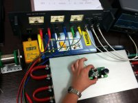
Personaly made measuring station for fast calibration and test procedure. 🙂
First cases will be received by GB members soon. Their comments will be most relevant, stay tuned.
Regards, L.C.
Hey LC can that chassis hold four modules for a fully balanced setup? Can I get away with two of Bruno's SMPS IE each SMPS drives two modules? Or am I basically setting fire to money... LOL
I plan to pair this with an Emotiva XMC-1 that has fully differential outs on the mains L/R so I figured it might as well take advantage of that and have a truly differential signal path from the converter to speaker level.
Here is an AP report on that processor if interested but requires a forum account.
XMC-1 Audio Precision Test Data | The Emotiva Lounge
Last edited:
Yes I'm working on this, Relaixed will be tested next week with the First One, will report and show pics. 😉
If this will be good combo I'll design a new PCB for preamp to fit in existing chassis, so it will be all SMD and super compact. 🙂
If you're also building preamps like the Relaixed I'm curious if your interesting is bring in and testing the Bent Audio Tap transformer based (Slagleformers IE Dave Slagle transformer volume attenuators) preamp with your amp.
BentAudio.com :: TAP
Last edited:
- Home
- Vendor's Bazaar
- First One - mosFET amplifier module