Thanks for your kind but undeserved words, BYRTT. L.C. last ground schematic is a good example of Evil's hunting requested, sometimes, by asymmetrical connections ;-)In meantime i enjoy asymmetrical and what it presents, though hehe tuning and evils hunting has been done for some time and mostly learnt from this domain, asymmetrical not so bad at all.
The 1K resistance reduce (in a great proportion) the ground leakage currents, while the diode ensure AC leakage voltages will never be upper than 0.7V around earth witch is totally safe for our fragile bodies.
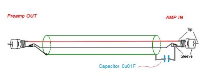
May I advise DIYers to try this kind of cabling for each channel asymmetrical audio cable from preamp to amp ?

@LC:
Is there any chance of a chassis/enclosure for an integrated amp?
Do you plan to test the Relaixed preamp with the FO modules?
I am still very much interested in an integrated implementation if I can make sure I can bring it to completion 🙂
Is there any chance of a chassis/enclosure for an integrated amp?
Do you plan to test the Relaixed preamp with the FO modules?
I am still very much interested in an integrated implementation if I can make sure I can bring it to completion 🙂
Improved schematic for stereo connection in a single chassis. GND potential of each channel is lifted from chassis earth potential, meaning connection is done via 1 k resistor and anti-parallel diodes.
Resembles the Loop Breaker Circuits of Rod Elliott (see bottom page)
Nice touch to make one for each channel so that the GND potentials of each channel are isolated

Any reasons why 1k instead of 10 ohm and no cap ?
Hi LC,
What is the total rail capacitance with one Hypex SMPS in circuit? It will help me adjust and balance it on my SMPS.
Also, what is the Capacitance in the primary side of the supply? Did you modify the power supplies as you have done for VSSA? Or you did keep the original state?
Thanks for your answer!
@LC:
Is there any chance of a chassis/enclosure for an integrated amp?
Do you plan to test the Relaixed preamp with the FO modules?
I am still very much interested in an integrated implementation if I can make sure I can bring it to completion 🙂
Yes I'm working on this, Relaixed will be tested next week with the First One, will report and show pics. 😉
If this will be good combo I'll design a new PCB for preamp to fit in existing chassis, so it will be all SMD and super compact. 🙂
Resembles the Loop Breaker Circuits of Rod Elliott (see bottom page)
Nice touch to make one for each channel so that the GND potentials of each channel are isolated
Any reasons why 1k instead of 10 ohm and no cap ?
Because it is GND lift. 😉
Hi LC,
What is the total rail capacitance with one Hypex SMPS in circuit? It will help me adjust and balance it on my SMPS.
Also, what is the Capacitance in the primary side of the supply? Did you modify the power supplies as you have done for VSSA? Or you did keep the original state?
Thanks for your answer!
SMPS1200A400 has 660 uF rail capacitance on the output and total 1000 uF in primary side.
I didn't touch any part, all original, left as it came from Hypex. 🙂
Because it is GND lift. 😉
Curious LC, is new wiring scheme compromise between first wiring scheme and floating amp PCB's, or is sound stream as good as floating.
Curious LC, is new wiring scheme compromise between first wiring scheme and floating amp PCB's, or is sound stream as good as floating.
Best sound is at complete GND to chassis earth isolation, so no DRD present. 😉
Since I don't want GND to be complete floating I tied GND from both channels to earth potential via DRD chain, always some compromise needed in this case for a safety reasons.
Although my demo amp, which I'm just listening at the moment, is in complete GND isolation.
Regards L.C.

Little fun LC, regarding post #851 we need built in little logic with sensor so that when humans within 1 meter of amp all GNDs/earth connections auto scheme to star ground with compromised audio stream, backing away more than 1 meter amp shifts from safety to audio nirvana. Also unfair TOSLINK can't help here.
Little fun LC, regarding post #851 we need built in little logic with sensor so that when humans within 1 meter of amp all GNDs/earth connections auto scheme to star ground with compromised audio stream, backing away more than 1 meter amp shifts from safety to audio nirvana. Also unfair TOSLINK can't help here.
No need to, chassis is still 100% earthed, fool proof. 😀

SMPS1200A400 has 660 uF rail capacitance on the output and total 1000 uF in primary side.
I didn't touch any part, all original, left as it came from Hypex. 🙂
Thanks for your detailed description LC!

May-be some little explanations should help some readers.
Let's look at your preamp. It is most of the time powered by a linear psu. primary of the transformer is plugged in AC. While the common point of the secondary is ground, and most of the time connected to earth.
There are parasitic capacitances between primary and secondary of the transformer (C ones are the best, ). A lot of evils comes across those capacitances, specially EMI RFI parasitic signals carried by AC. And because the earth wire is not a point, act like an antenna because its length, and don't have a real 0 impedance, the earth of the amp will never be at the exact earth potential.
Same thing occurs amp side. but with different evils. This means that, because the two earth will not be at the same potential between the two units, a current will flow in the ground wire of the audio cable between them, and this evil will be added to the pure signal and amplified by the amplifier as well.
The first thing to do is to disconnect the earth wire of your preamp, do not plug any device on it, and find the best sens of your AC wires (between hot and neutral) to have the less leakage voltages between chassis and earth plug. Done.
Now, you plug yopur amplifier, isolated and not connected to the preamp. And measure between the two audio grounds. Find the best AC sens of your amplifier this way. Do this shorting the resistance that L.C. cleverly added.
Now, remove those short circuits, and plug the units together.
Now, a little explanation of the L.C. earth arrangement. Without, there is a ground loop with ground and earth, because the two units are connected together by the ground of asymmetrical signal wire, and by the earth wires connected to the two chassis to the common earth plug, for safety reasons.
The 1K resistances (a lot higher than the cable impedance) isolate the two, and reduce the leakage currents to near none. While the diode ensure that, whatever can happens, the voltages between the two ground audio wires will never be higher than 0.7V (the diodes anode-cathode voltage), witch is safe for you. As the two chassis are connected to the AC earth, via the AC plug, you are twice protected.
And, as the leakages voltages are never as high than the 0.7V, the diode will never conduct in normal use, and the loop is broken by the 1K resistance, just used to ensure a ground reference when nothing is connected.
Hoping it helps and i was clear enough.
Can't speak for every one, helps a lot here..........Hoping it helps and i was clear enough.
 thanks.
Scary how much LAYOUT scheme sometimes influence SQ and makes one judge a circuit or system in a wrong or right way.
That's the funny part of the game 🙂Scary how much LAYOUT scheme sometimes influence SQ and makes one judge a circuit or system in a wrong or right way.
Good technical understanding of the various problems, intelligent solution to cure them, clever design,, and... a pinch of talent.
What i love in this unique art is it is based on science and technology, but this is only half of the story. The other one is feeling, sensitivity, musical knowledge, experience, search of the beauty and simplicity, modesty, and a lot of courage when you participate in forums in front of an army of robotic pure objectivists ;-)
As L.C. demonstrate daily, you can never be satisfied, always have something new to learn, discover, and improve, it is passionating.
Last edited:
- Home
- Vendor's Bazaar
- First One - mosFET amplifier module