Member
Joined 2009
Paid Member
Member
Joined 2009
Paid Member
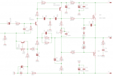
I'm sure you'll want to do a bit of tidying up - R4 should be zero as you say. It's function is relevant only for the 3 BJT input stage, not the simpler version you have shown with 2 BJTs (input device and VAS).
Also, for example, in your diagram R8 should be between the VAS output and emitter of the input device not in parallel with R10 as you have drawn it.
Also, for example, in your diagram R8 should be between the VAS output and emitter of the input device not in parallel with R10 as you have drawn it.
Hi Christian,
I would love to try building that one if you get it all worked out. Hopefully someone will be kind enough to do a foil layout for it.
Blessings, Terry
I would love to try building that one if you get it all worked out. Hopefully someone will be kind enough to do a foil layout for it.
Blessings, Terry
Gareth, good pick up, R8 is completely useless the way I had it wired in!
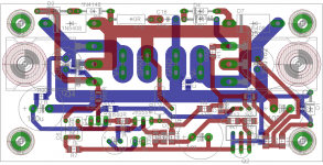
Terry, I'm about half way through laying this out in Eagle and will have some boards made up once done. You are welcome to the files but I would strongly suggest you wait until I've tested a prototype - this will be the first PCB I've designed and so I'm expecting problems. Becar in mind this Layout will be a mix of TH and SMT so it may be no good for you.
Terry, I'm about half way through laying this out in Eagle and will have some boards made up once done. You are welcome to the files but I would strongly suggest you wait until I've tested a prototype - this will be the first PCB I've designed and so I'm expecting problems. Becar in mind this Layout will be a mix of TH and SMT so it may be no good for you.
How about a nice simple version of TGM8 with a pair of lateral FETs?
I think VAS current is not enough to drive gate capacitance. It hurt the slew rate.
I hear what you are saying Bimo, but that hasn't stopped the VSSA brigade from hanging their latfets off the VAS transistors. My VSSA sounds rather good so there must be some merit to the idea.
I want to build something that sounds better than a VSSA but with fewer transistors 🙂
I want to build something that sounds better than a VSSA but with fewer transistors 🙂
I hear what you are saying Bimo, but that hasn't stopped the VSSA brigade from hanging their latfets off the VAS transistors. My VSSA sounds rather good so there must be some merit to the idea.
I want to build something that sounds better than a VSSA but with fewer transistors 🙂
Good luck with that
I hear what you are saying Bimo, but that hasn't stopped the VSSA brigade from hanging their latfets off the VAS transistors. My VSSA sounds rather good so there must be some merit to the idea.
I want to build something that sounds better than a VSSA but with fewer transistors 🙂
Yes. But Vas current on VSSA around 16mA. It is enough to drive latfets directly. If you want less current on Vas, you can add driver as emitter follower.
VAS current on this design is ~18mA.
how much voltage do you use for power supply?
My apologies Bimo; it's been a while since I worked out the value of a bootstrap current source and I screwed up the math.
I put the current at around 4.5mA with 35V rails (a long way off the 18mA I suggested earlier).
The output stage presented here is from Rod Elliott's P101 project. A combination befitting TGM8 since Bigun based it on the P3A.
In Rod's article he states:
So according to Rod, 5mA is adequate drive. We could increase the slew rate by doubling the VAS current to 10mA by reducing the bootstrap resistors to 1k5.
Thoughts?
I put the current at around 4.5mA with 35V rails (a long way off the 18mA I suggested earlier).
The output stage presented here is from Rod Elliott's P101 project. A combination befitting TGM8 since Bigun based it on the P3A.
In Rod's article he states:
The entire circuit has been optimised for minimum current in the Class-A driver, while still providing sufficient drive to ensure full power capability up to 25kHz. The slew rate is double that required for full power at 20kHz, at 15V/us, and while it is quite easy to increase it further, this amp already outperforms a great many other amps in this respect, and faster operation is neither required nor desirable.
In both versions of the amp, R7 and R8 are selected to provide 5mA current through the voltage amplifier stage. You will need to change the value to use a different supply voltage ...
So according to Rod, 5mA is adequate drive. We could increase the slew rate by doubling the VAS current to 10mA by reducing the bootstrap resistors to 1k5.
Thoughts?
My apologies Bimo; it's been a while since I worked out the value of a bootstrap current source and I screwed up the math.
I put the current at around 4.5mA with 35V rails (a long way off the 18mA I suggested earlier).
The output stage presented here is from Rod Elliott's P101 project. A combination befitting TGM8 since Bigun based it on the P3A.
In Rod's article he states:
So according to Rod, 5mA is adequate drive. We could increase the slew rate by doubling the VAS current to 10mA by reducing the bootstrap resistors to 1k5.
Thoughts?
We always make trade off between THD and slew rate. I suggest to do sim first before you build the amplifier. I think minimum full power bandwidth should be 159 kHz.
Does that equate to 50V/us for a 28.28Vac output?We always make trade off between THD and slew rate. I suggest to do sim first before you build the amplifier. I think minimum full power bandwidth should be 159 kHz.
Slew rate = Freq * Vac * Pi * 10^-6 (V/us)?
Last edited:
Does that equate to 50V/us for a 28.28Vac output?
Slew rate = Freq * Vac * Pi * 10^-6 (V/us)
I think slew rate = freq * Vp * 2 * Pi * 10^-6 (V/uS). But I am not sure, I must confirm it to Douglas Self's book.
- Home
- Amplifiers
- Solid State
- TGM8 - my best amplifier, incredible bass, clear highs, no fatigue (inspired by Rod Elliot P3a)