Please post your exact ASC so we can replicate, because the results look implausible.
You will need to include your models unless they are exact copies of Bob Cordell's.
Where are the TIP models from? my version of Cordell-Models does not show them.
Best wishes
David
Agree if thread opener could post the asc file others here could verify if it indeed is stable. From the THD plots it seems it possibly could.
This topology has been used by over 50 different models of yamaha amps so its perfectly feasible. Simmed THD is feasible too as the design uses two pole compensation.
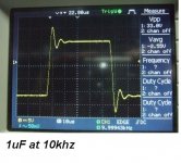
If the amplifier it is not perfect stabile , the settling time will be worse and what you will win it will lost very quickly. Settling time it is very important for the sound, like black in the tv-displays. In the photos are 2 amplifiers: one with LME49810 (470nF at 1khz) and second it is a proprietary design (1uF at 10khz). Maybe the THD measurements are just similar, under 0.001%, but.....
Attachments

Dear all,
Here are the asc file along with the models used. I believe the tip models come from this forum. You can find all others in the Cordel Models.
But please do not use the design in any business purposes. Wish you happy with the simulation and lucky in your diy.
.MODEL Qtip41c npn IS=7.55826e-11 BF=260.542 NF=1.11221 VAF=100 IKF=0.526814 ISE=1e-08 NE=2.18072 BR=26.0542 NR=1.5 VAR=1000 IKR=3.54059 ISC=1e-08 NC=1.63849 RB=4.56157 IRB=0.1 RBM=0.1 RE=0.0162111 RC=0.0810556 XTB=0.1 XTI=1 EG=1.206 CJE=1.93296e-10 VJE=0.4 MJE=0.259503 TF=1e-08 XTF=4.06972 VTF=7.1157 ITF=0.001 CJC=1.09657e-10 VJC=0.730921 MJC=0.23 XCJC=0.803085 FC=0.8 CJS=0 VJS=0.75 MJS=0.5 TR=9.01013e-08 PTF=0 KF=0 AF=1
.MODEL Qtip42c pnp IS=5.65618e-10 BF=120.073 NF=1.24004 VAF=90.6071 IKF=1.46498 ISE=6.98929e-14 NE=4 BR=2.83268 NR=1.30331 VAR=27.1221 IKR=10 ISC=6.98934e-14 NC=3.78125 RB=4.71382 IRB=0.234602 RBM=0.12691 RE=0.000666374 RC=0.0927424 XTB=3.21145 XTI=1 EG=1.05 CJE=1.93221e-10 VJE=0.4 MJE=0.259369 TF=9.99163e-09 XTF=4.41941 VTF=6.53488 ITF=0.001 CJC=1.0962e-10 VJC=0.731968 MJC=0.23 XCJC=0.799902 FC=0.799995 CJS=0 VJS=0.75 MJS=0.5 TR=1e-07 PTF=0 KF=0 AF=1
.model BD139 NPN(IS=1e-09 BF=222.664 NF=0.85 VAF=36.4079 IKF=0.166126 ISE=5.03418e-09 NE=1.45313 BR=1.35467 NR=1.33751 VAR=142.931 IKR=1.66126 ISC=5.02557e-09 NC=3.10227 RB=26.9143 IRB=0.1 RBM=0.1 RE=0.000472454 RC=1.04109 XTB=0.727762 XTI=1.04311 EG=1.05 CJE=1e-11 VJE=0.75 MJE=0.33 TF=1e-09 XTF=1 VTF=10 ITF=0.01 CJC=1e-11 VJC=0.75 MJC=0.33 XCJC=0.9 FC=0.5 CJS=0 VJS=0.75 MJS=0.5 TR=1e-07 PTF=0 KF=0 AF=1?VCEO=80 ICrating=1A MFG=Philips)
View attachment LowDistortion3StageVoltageFeedbackAmp.asc
Agree if thread opener could post the asc file others here could verify if it indeed is stable. From the THD plots it seems it possibly could.
This topology has been used by over 50 different models of yamaha amps so its perfectly feasible. Simmed THD is feasible too as the design uses two pole compensation.
Hi manso,
asc file posted in 42#.🙂
Please post your exact ASC so we can replicate, because the results look implausible.
You will need to include your models unless they are exact copies of Bob Cordell's.
Where are the TIP models from? my version of Cordell-Models does not show them.
Best wishes
David
Dave,
the asc file is posted in 42#. 🙂
Jazz.
Dave,
the asc file is posted in 42#. 🙂
Jazz.
what time it need to run ".tran" ?
Why you short R9? to measure open loop gain? why do you not use tian probe?
what time it need to run ".tran" ?
Why you short R9? to measure open loop gain? why do you not use tian probe?
bi bimo,
Thanks for finding the bug 😛. I will re-post the asc file . 20ms is the time used.
Jazz
There is a bug in the asc file in post42#.
Here is the corrected.
The amp as a super low THD at 1K but derate quickly to higher frequencies. I think the 10Khz THD it still acceptable.
View attachment LowDistortion3StageVoltageFeedbackAmp.asc
Here is the corrected.
The amp as a super low THD at 1K but derate quickly to higher frequencies. I think the 10Khz THD it still acceptable.
View attachment LowDistortion3StageVoltageFeedbackAmp.asc
...the asc file is posted in 42#....
Thank you.
Your BD139 model is very different from Bob Cordell's
Bob's models are usually considered reliable and yours does not look plausible.
Where does your model come from and why have you used it in preference to Bob's?
Best wishes
David
Last edited:
Thank you.
Your BD139 model is very different from Bob Cordell's
Bob's models are usually considered reliable and yours does not look plausible.
Where does your model come from and why have you used it in preference to Bob's?
Best wishes
David
Hi Dave,
The last line "MFG=Philips" tells this is a model for philips. I do not prefer this model over Bob's. I simply has used it for two years and it gave very similar performance in reality as in simulation.
This transistor does not matter much to the THD. I believe you can achieve similar THD with Bob's BD139 model. If you focus on this you will loose the sight of the whole.
Best Regards.
Jazz
still very odd bias choices, R35,36 off by 10x?
and VAS Ic 5x the driver Q Ic?
and unacceptable (nearly no) phase margin
and VAS Ic 5x the driver Q Ic?
and unacceptable (nearly no) phase margin
still very odd bias choices, R35,36 off by 10x?
and VAS Ic 5x the driver Q Ic?
and unacceptable (nearly no) phase margin
Hi jcx:
VAC Ic >> driver Ic is good for minimise the VAS load distortion. 😉 You have read Doug's book, should know it better.
Yes, as you have pointed, this circuit is not perfect.If you do not like some parts or choice of values, you can just post the one you like. The asc file is there for modification as your will. Diyers will appreciate your great work😀.
What I am afraid is that there is no way to make the THD lower while improving other characteristics.
Jazz
bi bimo,
Thanks for finding the bug 😛. I will re-post the asc file . 20ms is the time used.
Jazz
I mean, how long? I run it several minute and it only reach 0.x% simulation. May be you have powerful CPU.
I think it is oscillated. You should make phase margin >= 65 degre and gain margin >= 8 dB and then post the simulation file again.
If the amplifier it is not perfect stabile , the settling time will be worse and what you will win it will lost very quickly. Settling time it is very important for the sound, like black in the tv-displays. In the photos are 2 amplifiers: one with LME49810 (470nF at 1khz) and second it is a proprietary design (1uF at 10khz). Maybe the THD measurements are just similar, under 0.001%, but.....
Very interesting!!
So you think settling time is quite vivid?
I have a little story, there are fake OPA627's on the internet these days, a Russian person was curious and opened them up and took detailed pictures of the circuit. He identified it was some kind of Analog Devices chip, then he or someone else looks at the specs and found quite a lot of similarities to the OPA627, I think they had identical settling time.
In my listening, to this fake OPA627, I actually think it sounds pretty similar to the real OPA627, lol......
Thus, I became a little curious if my perceived similarity is correlated to the settling time spec. However, this is my only example for now, perhaps I will make an excel sheet later of op-amp's and perform a kind of blind test.
About 3 weeks ago I posted up my own schematic in the Analog Line Level forums here for a thread about discrete opamps. I put a note up at that time to whom I was talking to that I would only leave the schematic up for two days or else someone would eventually come along and call it there's (DIY dealers and the Chinese are the wost offenders for plagerizing).
Have some evidence that it's your design, like a dated forum post or dated internet site or something like that.
I've seen measurements which say that the discrete op-amp's by Burson are identical to the op-amp's by Audio-gd.
Either Audio-gd copied Burson or vice-versa.
Hi Kastor,
Thanks for your suggestions 😀. I do not doubt that amp performs better, especially in terms of s/r. But it is too complex for diyer. I will build the amp as posted in the openning post and call it JC2014.
Jazz
I'm just curious, is there a special reason the amp in that other thread looks too complex?
Good luck with your JC2014.

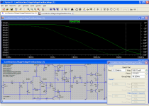
Use shorter timestep in transient analysis and you will see oscilations. AC stability analsis looks like attached. 80dB NFB at 20kHz is unrealistic, no chance to keep it stable..
Too bad news. Is it hopeless?🙁
Too bad news. Is it hopeless?🙁
Yes, If you don't modify it.
I think you don't need 0,000048% THD in audio amplifier.
First, You need a stable amplifier 😀
I will trade THD for slew rate. In my experience high slew rate amplifier always sound better.
Try attached modified asc file. Now are results realistic and it should be absolutely stable (big phase margin). And use better (faster, with lower Cob) VAS and driver transitors .Too bad news. Is it hopeless?
Attachments
Last edited:
Try attached modified asc file. Now are results realistic and it should be absolutely stable (big phase margin). And use better (faster, with lower Cob) VAS and driver transitors .
Your post is enlightening. Thanks a lot BV.
I have tried to increase the phase margin by simply change the C2/C7. Oddly, the transient simulation had the opposite outcome to the ac analysis, ie. when transient simulation show no oscillation, the ac analysis show bad phase margin; when ac analysis show good phase margin, the transient simulation show nasty oscillation.
Anybody know why? Is this a bug with LTspice or something?
This circuit transient OK, but bad phase margin

phase plot for the above circuit

1KHz FFT

This circuit good phase margin, but oscilate at xMHz

phase plot for the above circuit

Anybody know why? Is this a bug with LTspice or something?
This circuit transient OK, but bad phase margin
phase plot for the above circuit
1KHz FFT
This circuit good phase margin, but oscilate at xMHz
phase plot for the above circuit
- Status
- Not open for further replies.
- Home
- Amplifiers
- Solid State
- THD=0.000048% Voltage Feedback Amp