phase margin at open loop gain
Hi Bigun,
Open loop gain would be more than 130db. How to make it at unity?
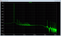
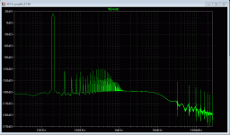
This is the simulation result for open loop. I need to have phase margin plots of some other prooven circuits to compare with.
If you have such plots, I will appreciate that you post some here. Thank you😀
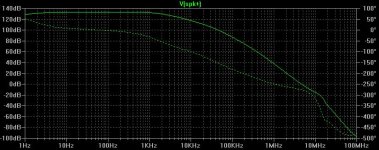
how much phase margin do you have at unity open loop gain ?
Hi Bigun,
Open loop gain would be more than 130db. How to make it at unity?
This is the simulation result for open loop. I need to have phase margin plots of some other prooven circuits to compare with.
If you have such plots, I will appreciate that you post some here. Thank you😀

you could save some time by reading a later edition of Self's Audio Power Amplifier design book, and Cordell's too
I really doubt that circuit is up to it in the real world
then there is the learning curve on physical implementation, layout, supply/gnd routing, bypassing
don't expect to get there in one try
Hi jcx, what specifically you doubt at? The THD figures sounds too good to be real to me too. But I never know unless somebody or myself try or buck the spice simulation methodology.
Even if it is 7 volt below 48 volt, it close to the limit of VCE max.
I sim it, it not working. It seem the CCS of VAS is too high.
Which transistor are you refering to?
MJE340/350 should be ok for 48x2 volt.
The voltage across LTP should be lower than 46volt by my simulation.
somebody - several somebodies in fact have tried, published results of built hardware
Douglas Self's Audio Power Amplifier Design Handbook for instance - especially recent editions have many AP plots of variations on each amplifier stage, works out his named distortions relative magnitudes
His plots for roughly the OP topology (and with better sized, better performing Q in several positions) are at best just breaking below 10 ppm 1 kHz THD - 10x worse than the OP sim
Cordell's book is good too for sometimes differing perspective and reinforcement of where they both agree
both would fault the ultimate low distortion capability of 2 stage BJT EF, single output Qs
if you read the PGP thread I linked you will find the assertion that even with advanced "error correction" output stage improving the limit - then bootstrap cascading the input diff pair Q is required to break below 1 ppm
Last edited:
bimo
Mistake in sch.asc.. Missing connection B-C Q6.
I am sorry.
This is an update.
Not sufficient phase margin and oscillated.
Attachments
Well, this is actually what the trade-off is about...
Open loop gain is 130 db. Closed loop gain you want to achieve would be something like 29 db. So, you have to "kill" more than 100 db with the global NFB. In such situation, almost any circuit, even with horrible open-loop linearity, will show excellent THD with the loop being closed. However, the problem is - it will tend to oscillate badly. I'm not saying it will be impossible to stabilize it, but rather difficult for sure, most likely jeopardizing some other important parameters, like slew rate and/or inter-modulation distortion (very important for sound quality!), audio bandwidth phase response, etc. So... low THD is a good thing to have, but in a proper balance with the other qualities.
Cheers,
Valery
Well, this is actually what the trade-off is about...
Open loop gain is 130 db. Closed loop gain you want to achieve would be something like 29 db. So, you have to "kill" more than 100 db with the global NFB. In such situation, almost any circuit, even with horrible open-loop linearity, will show excellent THD with the loop being closed. However, the problem is - it will tend to oscillate badly. I'm not saying it will be impossible to stabilize it, but rather difficult for sure, most likely jeopardizing some other important parameters, like slew rate and/or inter-modulation distortion (very important for sound quality!), audio bandwidth phase response, etc. So... low THD is a good thing to have, but in a proper balance with the other qualities.
Cheers,
Valery
Hi Valery,
I agree with you very much. There must be a trade off between THD, IMD, and s/r. But what I think: isn't THD0.000048 a good start point for this trade off? Cheers.
Jazz
Last edited:
somebody - several somebodies in fact have tried, published results of built hardware
Douglas Self's Audio Power Amplifier Design Handbook for instance - especially recent editions have many AP plots of variations on each amplifier stage, works out his named distortions relative magnitudes
His plots for roughly the OP topology (and with better sized, better performing Q in several positions) are at best just breaking below 10 ppm 1 kHz THD - 10x worse than the OP sim
Cordell's book is good too for sometimes differing perspective and reinforcement of where they both agree
both would fault the ultimate low distortion capability of 2 stage BJT EF, single output Qs
if you read the PGP thread I linked you will find the assertion that even with advanced "error correction" output stage improving the limit - then bootstrap cascading the input diff pair Q is required to break below 1 ppm
Hi jcx,
Thank you for your information. Douglas' and Bob's literature certainly worth reading. I remember in the "Audio Power Amplifier Design Handbook", The book suggested many methods to eliminate the distortions at the input, vas, op stages. But I do not have components or time to try all these advanced methods. Especially, how many diyer have a AP to verify those improvements? I am not saying that methods not good, but I think it impractical for diyer to try. If you look at the input of the bootstrap cascaded input stage, the number of components of such a single stage equals a whole amp. What I hope is an amp with good performance but also easy to realise.
Jazz
Last edited:
THD=0.000048% Voltage Feedback Amp
Hi
How do you think about the below circuit? Simulation shows super low THD. Is it realistic to build such an amp?
View attachment 428495
View attachment 428496
View attachment 428497
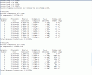
Fourier components of V(spk+)
DC component:0.0472742
Harmonic Frequency Fourier Normalized Phase Normalized
Number [Hz] Component Component [degree] Phase [deg]
1 1.000e+03 4.167e+01 1.000e+00 -0.13? 0.00?
2 2.000e+03 1.000e-05 2.400e-07 -69.14? -69.00?
3 3.000e+03 1.485e-05 3.564e-07 78.78? 78.92?
4 4.000e+03 6.596e-06 1.583e-07 177.53? 177.66?
5 5.000e+03 2.569e-06 6.165e-08 -111.33? -111.20?
6 6.000e+03 2.553e-06 6.126e-08 163.10? 163.24?
7 7.000e+03 2.560e-06 6.143e-08 171.02? 171.15?
8 8.000e+03 2.647e-06 6.351e-08 177.27? 177.40?
9 9.000e+03 1.273e-06 3.054e-08 -148.23? -148.10?
Total Harmonic Distortion: 0.000048%
Hi jcx, what specifically you doubt at? The THD figures sounds too good to be real to me too. But I never know unless somebody or myself try or buck the spice simulation methodology.
I am sorry.
This is an update.
Not sufficient phase margin and oscillated.
The classic flaw of this schematic and the reason it is showing such a)low
distortion and b) poor stability is simple:
The 100p Miller compensation is across only half of the Baxandall Pair, as such the B.P. essentially defeats it completely, just like it defeats the
Cob of that transistor.
Strap the 100p across both Q1 and Q12.
On the other side, no need for the 100p, it's just a current source.
If anything this baxandall pair CCS may need some taming with a base stopper on Q10.
I re ran the sim as such and the distortion is around 0.01 at 28V peak / 8
ohm.
Oh well no free lunch 🙂
Z
Bimo's simulation show oscillation because his drawing, as BV pointed out in post16#, was wrong. 😉The classic flaw of this schematic and the reason it is showing such a)low
distortion and b) poor stability is simple:
The 100p Miller compensation is across only half of the Baxandall Pair, as such the B.P. essentially defeats it completely, just like it defeats the
Cob of that transistor.
Strap the 100p across both Q1 and Q12.
On the other side, no need for the 100p, it's just a current source.
If anything this baxandall pair CCS may need some taming with a base stopper on Q10.
I re ran the sim as such and the distortion is around 0.01 at 28V peak / 8
ohm.
Oh well no free lunch 🙂
Z
My simulation does not show advantage of changing the position of the miller cap. The amp does not oscillate either 1k or 20khz. But the phase margin was not good, that I recognise.
Thank you for your suggestions and your ideas. 😀
THD=0.000048% Voltage Feedback Amp
How do you think about the below circuit? Simulation shows super low THD. Is it realistic to build such an amp?
View attachment 428495
View attachment 428496
View attachment 428497
Nice pictures.
Yes, please try to build it! Have a look at this thread as well with even lower specs than you achieved
http://www.diyaudio.com/forums/solid-state/255236-opamp-based-power-amp.html
About 3 weeks ago I posted up my own schematic in the Analog Line Level forums here for a thread about discrete opamps. I put a note up at that time to whom I was talking to that I would only leave the schematic up for two days or else someone would eventually come along and call it there's (DIY dealers and the Chinese are the wost offenders for plagerizing). Oddly, this looks almost identical to my design, but mine was stable and included an ERCO amp on the output and switching mute circuit on the input.
Last edited:
About 3 weeks ago I posted up my own schematic in the Analog Line Level forums here for a thread about discrete opamps. I put a note up at that time to whom I was talking to that I would only leave the schematic up for two days or else someone would eventually come along and call it there's (DIY dealers and the Chinese are the wost offenders for plagerizing). Oddly, this looks almost identical to my design, but mine was stable and included an ERCO amp on the output and switching mute circuit on the input.
Hi kouiky,
This is my independent work. The basic idea comes from my recent study on Naim NAP140 and Apex AX-14. I never see anything of your published work. But my own idea is to increase the open look gain by using very high hfe vas transistors and minimise the input&output capacitance. Is this also your idea?😉 What is your THD figures?
Kind Regards.
Jazz
The amp as posted in the openning post does not oscilate, at least in the spice simulation, although stability for such a high gain amp is always something that people can debate.
Nice pictures.
Yes, please try to build it! Have a look at this thread as well with even lower specs than you achieved
http://www.diyaudio.com/forums/solid-state/255236-opamp-based-power-amp.html
Hi Kastor,
Thanks for your suggestions 😀. I do not doubt that amp performs better, especially in terms of s/r. But it is too complex for diyer. I will build the amp as posted in the openning post and call it JC2014.
Jazz
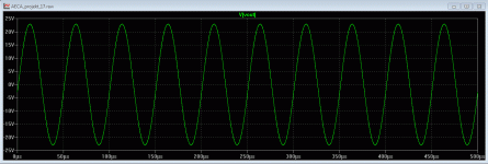
It is unstable (in LTspice simulation). Output signal is modulated by hf instability. Build it and try, reality is what counts, simulation is sometimes too optimistic...
It is unstable (in LTspice simulation). Output signal is modulated by hf instability. Build it and try, reality is what counts, simulation is sometimes too optimistic...
Agree, spice models are great fun, but reality is what counts. Or more important, sound is what counts.
Here what spice simulation shows on well tuned piece of amp: 🙂
But it is worth to build it just to see what happens.
Attachments
My simulation does not show...
The amp does not oscillate either 1k or 20khz...
Please post your exact ASC so we can replicate, because the results look implausible.
You will need to include your models unless they are exact copies of Bob Cordell's.
Where are the TIP models from? my version of Cordell-Models does not show them.
Best wishes
David
Bimo's simulation show oscillation because his drawing, as BV pointed out in post16#, was wrong. 😉
My simulation does not show advantage of changing the position of the miller cap. The amp does not oscillate either 1k or 20khz. But the phase margin was not good, that I recognise.
Thank you for your suggestions and your ideas. 😀
No worries.
I suggest a/ study understand function of Baxandall pair, they are very
useful but have a specific function. b/ do a bode plot of loop gain versus
phase.
Get your phase margin / stability properly sorted first, check square wave
response, then go for low distortion.
It will have a better chance of sounding good.
T
- Status
- Not open for further replies.
- Home
- Amplifiers
- Solid State
- THD=0.000048% Voltage Feedback Amp

