THD=0.000048% Voltage Feedback Amp
Hi
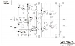
How do you think about the below circuit? Simulation shows super low THD. Is it realistic to build such an amp?


Fourier components of V(spk+)
DC component:0.0472742
Harmonic Frequency Fourier Normalized Phase Normalized
Number [Hz] Component Component [degree] Phase [deg]
1 1.000e+03 4.167e+01 1.000e+00 -0.13? 0.00?
2 2.000e+03 1.000e-05 2.400e-07 -69.14? -69.00?
3 3.000e+03 1.485e-05 3.564e-07 78.78? 78.92?
4 4.000e+03 6.596e-06 1.583e-07 177.53? 177.66?
5 5.000e+03 2.569e-06 6.165e-08 -111.33? -111.20?
6 6.000e+03 2.553e-06 6.126e-08 163.10? 163.24?
7 7.000e+03 2.560e-06 6.143e-08 171.02? 171.15?
8 8.000e+03 2.647e-06 6.351e-08 177.27? 177.40?
9 9.000e+03 1.273e-06 3.054e-08 -148.23? -148.10?
Total Harmonic Distortion: 0.000048%
20140719 the spice asc file and models are posted in 42#
20141021 The quasi-complementary mosfet output simulation and implementation results are in post 83#
Hi
How do you think about the below circuit? Simulation shows super low THD. Is it realistic to build such an amp?
Fourier components of V(spk+)
DC component:0.0472742
Harmonic Frequency Fourier Normalized Phase Normalized
Number [Hz] Component Component [degree] Phase [deg]
1 1.000e+03 4.167e+01 1.000e+00 -0.13? 0.00?
2 2.000e+03 1.000e-05 2.400e-07 -69.14? -69.00?
3 3.000e+03 1.485e-05 3.564e-07 78.78? 78.92?
4 4.000e+03 6.596e-06 1.583e-07 177.53? 177.66?
5 5.000e+03 2.569e-06 6.165e-08 -111.33? -111.20?
6 6.000e+03 2.553e-06 6.126e-08 163.10? 163.24?
7 7.000e+03 2.560e-06 6.143e-08 171.02? 171.15?
8 8.000e+03 2.647e-06 6.351e-08 177.27? 177.40?
9 9.000e+03 1.273e-06 3.054e-08 -148.23? -148.10?
Total Harmonic Distortion: 0.000048%
20140719 the spice asc file and models are posted in 42#
20141021 The quasi-complementary mosfet output simulation and implementation results are in post 83#
Last edited:
"How do you think about the below circuit? Simulation shows super low THD. Is it realistic to build such an amp?"
no, it's mandatory 🙂
no, it's mandatory 🙂
Member
Joined 2009
Paid Member
you could save some time by reading a later edition of Self's Audio Power Amplifier design book, and Cordell's too
I really doubt that circuit is up to it in the real world
then there is the learning curve on physical implementation, layout, supply/gnd routing, bypassing
don't expect to get there in one try
I really doubt that circuit is up to it in the real world
then there is the learning curve on physical implementation, layout, supply/gnd routing, bypassing
don't expect to get there in one try
VCE max. of BC550C is 45V and you use +-48V power supply.
Usually if you looking for low THD, you get low slew rate.
In my last design of such topology, first I looking for highest slew rate, then lowest THD20.
Usually if you looking for low THD, you get low slew rate.
In my last design of such topology, first I looking for highest slew rate, then lowest THD20.
Bimo, VAS is Yamaha style, if I'm seeing correctly, so it's the larger transistors setting the higher voltages,
Putting from small phone, will look more at home
Putting from small phone, will look more at home
Bimo, VAS is Yamaha style, if I'm seeing correctly, so it's the larger transistors setting the higher voltages,
Putting from small phone, will look more at home
I mean LTP transistors Q11 and Q12. These transistor will see almost 48V.
And VAS transistor is better use low Cob to get low THD20.
"good reputation" and sub ppm THD are unrelated in audio
there are a few projects here that have tested hardware builds with sub ppm THD - lots rarer that those with reputations
maybe your journey could be shorter than http://www.diyaudio.com/forums/solid-state/110760-pgp-pretty-good-poweramp.html#post1335080
try seeing how much you understand of the issues they discuss, how much you need to learn
I mean LTP transistors Q11 and Q12. These transistor will see almost 48V.
And VAS transistor is better use low Cob to get low THD20.
On the contrary, they will see much less than 48 volts. 😉
Vas is a baxandall pair, Cob here doesnt contribute significantly to high frequency THD.
Last edited:
On the contrary, they will see much less than 48 volts. 😉
Vas is a baxandall pair, Cob here doesnt contribute significantly to high frequency THD.
Did you simulated the schematic? What the value of collector - emitter voltage of LTP when no signal?
Did you simulated the schematic? What the value of collector - emitter voltage of LTP when no signal?
No I didnt simulate, but experience tells me it will at least be 6 or 7 volts below Vcc.
No I didnt simulate, but experience tells me it will at least be 6 or 7 volts below Vcc.
Even if it is 7 volt below 48 volt, it close to the limit of VCE max.
I sim it, it not working. It seem the CCS of VAS is too high.
Attachments
No I didnt simulate, but experience tells me it will at least be 6 or 7 volts below Vcc.
I sim it...
Don't even need to sim it, you are correct unless the VAS is so bad that the circuit wouldn't work anyway.
Just by inspection the Vce of the LTP will be about 1 V less than Vcc, close to 47 V. The LTP current source is also close to this, about a Vbe less, say 46 V.
The circuit is a poor copy of a "blameless", Mr Self deserves better.
Best wishes
David.
Last edited:
To put things in perspective here
10uA glowing through 0.1 Ohm is 1uV
1uV of 2nd harmonic on a ground return is -120 dB ref 1V signal = 1ppm (0.0001%).
10's of uA flowing through sub 1 Ohm resistances on ground tracks is a common occurence in amplifiers.
So, better to spend much effort on thinking about the practicalities of building a sub ppm amplifier - the realities are that it is extrmely difficult and its not the circuit topology thats the limiting factor in most cases, but the implementation.
Also, keep in mind you will not be able to distinguish between 0.005 and .001 distortion. A good pair of ears and some practice and you may be able to do it reliably at 0.1%.
Dont get hung up on THD.
Dont get hung up on THD.
Yes, I agree.
Usually I will trade THD for slew rate 😀
Yes, I agree.
Usually I will trade THD for slew rate 😀
I will trade slew rate for a combination of amplifier and speakers that sound good to my ears.
"How do you think about the below circuit? Simulation shows super low THD. Is it realistic to build such an amp?"
no, it's mandatory 🙂
😀
Hope you really mean that is a good project to start.
I am drawing the PCB. Would you like to build it if there is a PCB for this circuit? Any other suggestions?
I will trade slew rate for a combination of amplifier and speakers that sound good to my ears.
Both JLH1969 and Naim Nap140 have not high s/r. But they both sounds good to my ears, more musical.
I also like amp with high s/r, they sound more transparent.
When I listen to jazz or vocal, I prefer to use amps like JLH1969/Nap140. When I listen to classics, especially those latest digital recordings, I prefer to use higher s/r amps.
What I never heard is an amp with super low THD and a realistic s/r to reproduce most jazz, vocal, classics with fidelity. I wish I could have such an amp.
- Status
- Not open for further replies.
- Home
- Amplifiers
- Solid State
- THD=0.000048% Voltage Feedback Amp