If you want it smaller and LF extension at the same time, a path with decreasing CSA would be shorter, overall size would be smaller, too, of course. Lower efficiency, though. And it'd be more of a (ML)TL than a horn, oh well...
You'd need it longer and overall larger to get the same LF extension with expanding path (normal horn). And it gives better efficiency.
You'd need it longer and overall larger to get the same LF extension with expanding path (normal horn). And it gives better efficiency.
You don't need dual 18 in in PPTH to achieve what you need. If you want it relatively deep and efficient there is not enough room unless you do something like a push-push TH with drivers face to face and rotated 90 deg so that magnets are on both sides of the exposed mouth chamber similar to idea Sine146 had in another post. However that removes second order distortion compensation of the push pull setup.
Last edited:
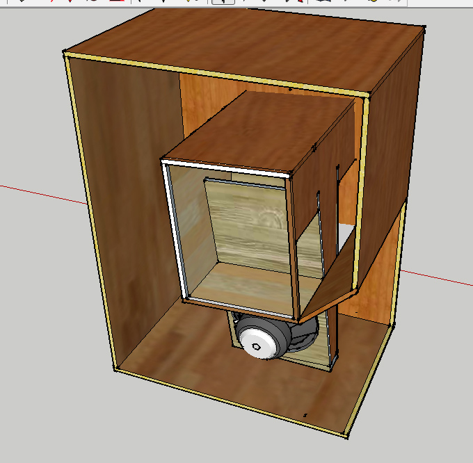
I think I got it - push-pull slot loaded tapped pipe (with a little horn at the mouth) in 100cm x 100cm x 60cm enclosure. I drew it first on grid paper this time, the measurements should be pretty accurate. Picture is a crude sketch.
Pipe's total lenght ~295cm (1/4 WL ~29Hz). Compression ratio at the slot is around 2:1 (1150cm2*2 : 1197cm2).
Mouth's type has many possibilities to possibly experiment with:
Maybe even some Kalsonator influence:
I think it looks pretty good, what do you guys think?
By the way, regarding the stuffing of the TH/TP, here's some interesting article about it: The Subwoofer DIY Page v1.1 - Projects : A "Proof of Concept" tapped pipe** - introduction

Pipe's total lenght ~295cm (1/4 WL ~29Hz). Compression ratio at the slot is around 2:1 (1150cm2*2 : 1197cm2).
Mouth's type has many possibilities to possibly experiment with:
An externally hosted image should be here but it was not working when we last tested it.
Maybe even some Kalsonator influence:
An externally hosted image should be here but it was not working when we last tested it.
An externally hosted image should be here but it was not working when we last tested it.
An externally hosted image should be here but it was not working when we last tested it.
An externally hosted image should be here but it was not working when we last tested it.
An externally hosted image should be here but it was not working when we last tested it.
I think it looks pretty good, what do you guys think?
By the way, regarding the stuffing of the TH/TP, here's some interesting article about it: The Subwoofer DIY Page v1.1 - Projects : A "Proof of Concept" tapped pipe** - introduction
Last edited:
Legis,
Interesting concept with the tapped pipe. Although we know you can fold a horn that reaches much lower and has better efficiency into the 1 meter square footprint why would you want to go the Tapped Pipe approach?
I like the sketches you made showing he pipe folding and how it comes to the front.
X
Interesting concept with the tapped pipe. Although we know you can fold a horn that reaches much lower and has better efficiency into the 1 meter square footprint why would you want to go the Tapped Pipe approach?
I like the sketches you made showing he pipe folding and how it comes to the front.
X
Legis,
Although we know you can fold a horn that reaches much lower and has better efficiency into the 1 meter square footprint why would you want to go the Tapped Pipe approach?
What design you mean by that?
With 18N860 that is pretty much among the best sensitivity (~110dB/2,83V 1Pi) what I have got with various foldings of this size. Changing from pipe to horn does not change much (if anything) in sensitivity department at least in those variations I have tried. Anechoic response to 20Hz is not required, in-room response of 20Hz - 100Hz is.
Pros could be that this kind of tapped pipe is easy to construct, it also allows the traditional push-pull slot loading arrangement where the drivers are closely coupled.
Last edited:
The Othorn with your driver. It only needs one though to reach 130 dB. When running to 110dB stroke will be low so HD is low rather than use dual drivers to reduce HD.
The Othorn with your driver. It only needs one though to reach 130 dB. When running to 110dB stroke will be low so HD is low rather than use dual drivers to reduce HD.
I simmed only with 150w power, here is 2000W/19mm (1pi):
An externally hosted image should be here but it was not working when we last tested it.
Out of curiosity I could try to sim the Othorn with hornresp and compare them, and/or you could try that PP SL tapped pipe with Akabak. Did you use this kind of folding data of Othorn: The Othorn tapped horn - AVS Forum
Legis,
Yes, that is exactly where I got the AkAbak script from then I modified it to accept the 18N860 by scaling CSA smaller to 0.867 but leaving lengths the same to keep the bass extension. I can run sim of tapped pipe for you. That is easy just get me the length you want and CSA and a horn expansion on end if you want. You should install AkAbak and I will get you the script to play with.
Yes, that is exactly where I got the AkAbak script from then I modified it to accept the 18N860 by scaling CSA smaller to 0.867 but leaving lengths the same to keep the bass extension. I can run sim of tapped pipe for you. That is easy just get me the length you want and CSA and a horn expansion on end if you want. You should install AkAbak and I will get you the script to play with.
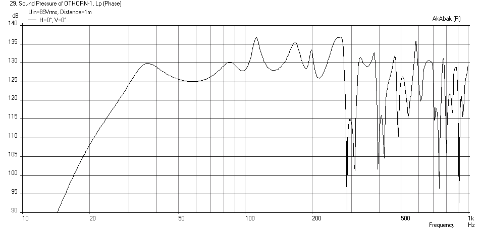
Stock-design Othorn does not look pretty in Hornresp with 18N860, it would clearly need some "fine" (major) tuning.
Ragged response both in pass band and above, big group delay spikes because of that and also noticeably more phase distortion/shift in the pass band.
Everything else was kept the same besides the different horn and in Othorn there is only 1pcs of 18N860. Changing the VTC and ACT like suggested in the mentioned AVS forum's opeing post, did not change anything so I kept them at zero.
The ragged response was also present in simulation you did with Akabak. It's quite similar to hornresp's graph actually, I'm impressed by the similarity!
I just don't understand how this is a good result compared to PP SL TP. 🙂
Ragged response both in pass band and above, big group delay spikes because of that and also noticeably more phase distortion/shift in the pass band.
Everything else was kept the same besides the different horn and in Othorn there is only 1pcs of 18N860. Changing the VTC and ACT like suggested in the mentioned AVS forum's opeing post, did not change anything so I kept them at zero.
An externally hosted image should be here but it was not working when we last tested it.
An externally hosted image should be here but it was not working when we last tested it.
An externally hosted image should be here but it was not working when we last tested it.
The ragged response was also present in simulation you did with Akabak. It's quite similar to hornresp's graph actually, I'm impressed by the similarity!
I just don't understand how this is a good result compared to PP SL TP. 🙂
doing this introduces a large error at the throat via the volume in the cones. With the B&C 21 mounted on 18mm ply the volume in each cavity is >10l. Going push pull neutralizes the majority of the error.
Cone volume normalized to the width of the Othorn expressed as CSA expansion:

Last edited:
Here, quite good prediction.
An externally hosted image should be here but it was not working when we last tested it.
"Maybe even some Kalsonator influence:"
That's what Art Welter was investigating when he came up with his Keystone design.
That's what Art Welter was investigating when he came up with his Keystone design.
Anechoic response to 20Hz is not required, in-room response of 20Hz - 100Hz is.
As far as I can see, your design is 20dB down at 20Hz. Do you really think this will be compensated by the room? Besides, many people prefer a rising curve at the low end, which would mean even more need for room gain.
Frode
As far as I can see, your design is 20dB down at 20Hz. Do you really think this will be compensated by the room? Besides, many people prefer a rising curve at the low end, which would mean even more need for room gain.
Frode
I'm eq'ing the rest if room leaves the bottom end too light (the capacity at 20Hz is very good). -20dB@20Hz for closed box is not uncommon either in anechoic.
Btw. the Othorn is also 20dB down at 20Hz with 18N860/862, but with much more ragged response. PPSLTP has almost the same simulated capacity at 20Hz than (dual) Othorn. (~117dB for 2x18N860 is PPSLTP vs ~113dB for single 18N860 in Othorn, edit. now both 1pi). PPSLTP could be made somewhat longer if it's wanted optimize otherwise. Making the pipe for example 40cm longer would still have 100Hz extension, somewhat better extension at the bottom end and 122dB capacity at 20Hz. But there is no free luch, more phase distortion, higher group delay spikes and slightly lower sensitivity >40Hz.
In general I regard sound quality much higher priority compared to "the last word" in anechoic extension. However I wouldn't consider making band-limited speakers of this size either.
Last edited:
I can run sim of tapped pipe for you. That is easy just get me the length you want and CSA and a horn expansion on end if you want. You should install AkAbak and I will get you the script to play with.
Hi X, did you run any sims of the tapped pipe yet? The lenght of pipe and other variables I used are visible in this picture:
An externally hosted image should be here but it was not working when we last tested it.
So the total lenght I simmed was 295cm, the slot (and good part of the pipe) had an area of 1197cm2 and the mouth was 4161cm2 (= 2 x 2080,5cm2, which is the area of one mouth). You could try sim it like this, without "horn expansion" at the mouth or any mouth shaping (like Kalsonator) for the sake of simplicity.
An externally hosted image should be here but it was not working when we last tested it.
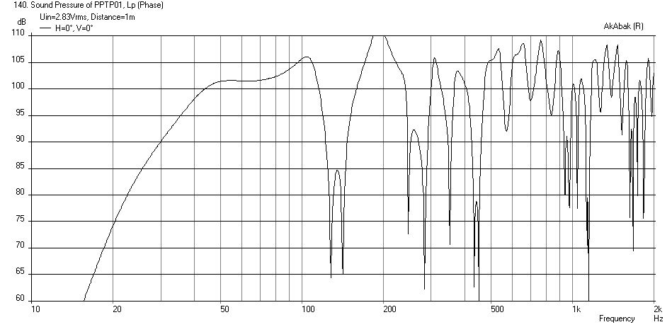
Sim of Legis PP Tapped Pipe with dual BMS 18NW860
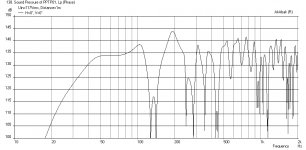
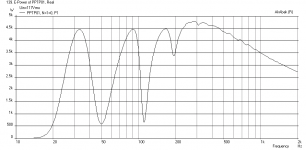
Here is the sim of the Push-Pull Tapped Pipe with dimensions provided by Legis in previous post. This tapped pipe has very high SPL capability, with 19 mm xmax reached at 117 volts (drivers in parallel for nominal 4 ohm load). The bass extension starts to fall at 50 Hz, so I think that the horn needs to be longer if you want to get good response to 30 Hz.
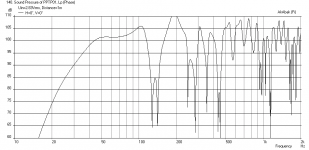
Here is SPL at 2.83v and 1m into 2pi space with speaker sitting on floor:
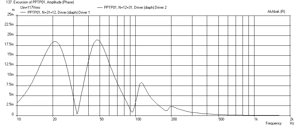
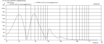
Here is cone displacement with 117 volts to reach 19 mm xmax (using 23Hz -24dB/oct HPF):
Here is corresponding SPL at xmax:

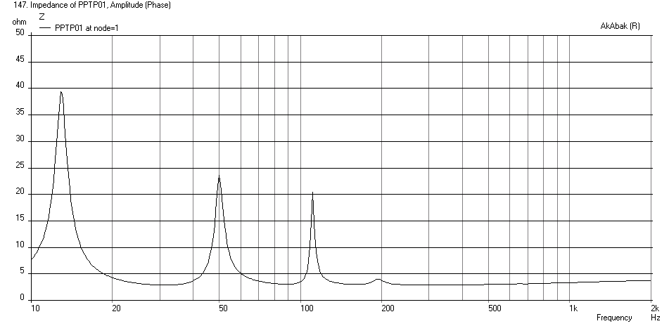
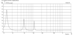
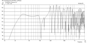
Here is Impedance:
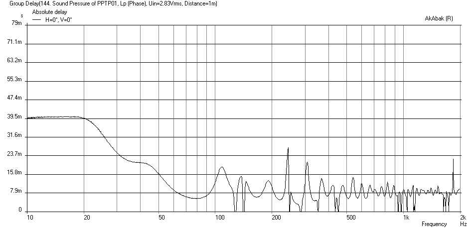
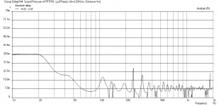
Here is Group Delay:
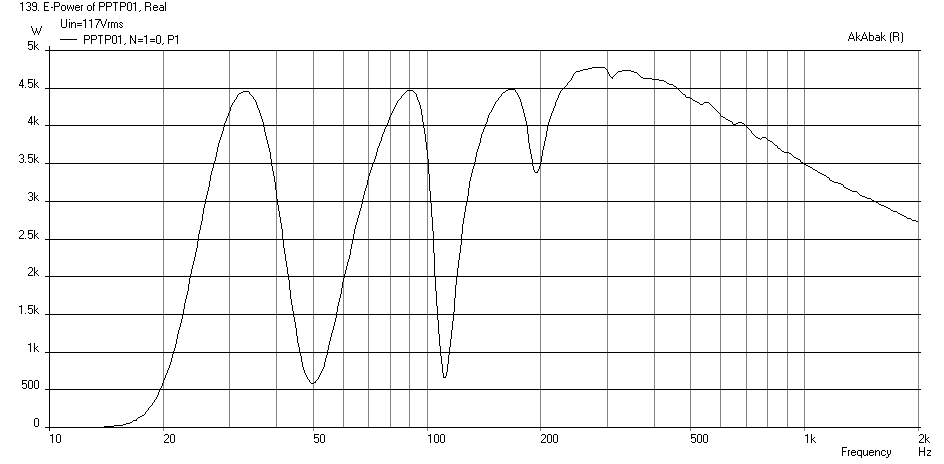
Here is Electrical Power delivered to both drivers (4.5kW+ - Yikes!!!):
However, if you mass load it by constricting the terminus according to:
From straight pipe at 1198 cm2 to 900 cm2 at driver backs
and 900 cm2 to 700 cm2 from driver backs to mouth, you can get the bass to extend well into the 20Hz and 85 volts is required to reach xmax of 19mm:

And here is the Code if you want to play with it:
Here is the sim of the Push-Pull Tapped Pipe with dimensions provided by Legis in previous post. This tapped pipe has very high SPL capability, with 19 mm xmax reached at 117 volts (drivers in parallel for nominal 4 ohm load). The bass extension starts to fall at 50 Hz, so I think that the horn needs to be longer if you want to get good response to 30 Hz.
Here is SPL at 2.83v and 1m into 2pi space with speaker sitting on floor:
Here is cone displacement with 117 volts to reach 19 mm xmax (using 23Hz -24dB/oct HPF):
Here is corresponding SPL at xmax:
Here is Impedance:
Here is Group Delay:
Here is Electrical Power delivered to both drivers (4.5kW+ - Yikes!!!):
However, if you mass load it by constricting the terminus according to:
From straight pipe at 1198 cm2 to 900 cm2 at driver backs
and 900 cm2 to 700 cm2 from driver backs to mouth, you can get the bass to extend well into the 20Hz and 85 volts is required to reach xmax of 19mm:
And here is the Code if you want to play with it:
Code:
| Push Pull Slot Loaded Tapped Pipe for Legis
| July 17, 2014
| by xrk971

System 'PPTP01'  | *** System: Push Pull Tapped Pipe 01 ***

Def_Const
{

| *** Define placement and size for reflections and baffle diffraction effects
Speaker_pos=0.32;  | Height of centerline of exit port above floor in meters (set large for 4pi)
Width=1.00;        | Width of cabinet external in meters
Height=0.64;       | Height of cabinet external in meters
Depth=1.00;        | Depth of cabinet in meters
Dist_wall=1000;    | Distance from wall in meters (set large to remove back wall reflections)

| **** define tapped pipe geometry ***

| *** Duct from closed end to driver ***
S1=1197*0.0001;  | duct CSA in cm^2
L1=25*0.01;      | duct length in cm

| *** Duct from driver faces thru long section to expansion start
S2=1197*0.0001;  | duct CSA in cm^2
L2=210*0.01;      | duct length in cm

| *** Waveguide from expansion start to driver backs (tap)
STh3=1197*0.0001;  | WG throat CSA in cm^2
SMo3=4161*0.0001;  | WG mouth CSA in cm^2
L3=35*0.01;        | WG length in cm

| *** Waveguide from driver backs (tap) to mouth exit
STh4=4161*0.0001;  | WG throat CSA in cm^2
SMo4=4162*0.0001;  | WG mouth CSA in cm^2  (waveguide needs to expand cannot be straight)
L4=25*0.01;        | WG length in cm

}

Def_Driver  'BMS18N860'  | BMS 18 in pro sub Qts 0.37, 19 mm xmax, 95 dB, 1500watts
  SD=1213cm2   |Piston
  fs=24.85Hz
  Qms=5.33
  Qes=0.40
  Mms=277g
  Re=5.70ohm
  Le=0.81mH
  Bl=24.93Tm
  Vas=304L

| *** set high pass filter to protect speaker over excursion xmax is 19 mm

Filter    'High Pass'  | 4th order Butterworth -24dB/oct, set freq with fo
    fo=23.0Hz  vo=1.0
    {b4=1;
     a4=1;  a3=2.613126;  a2=3.414214;  a1=2.613126;  a0=1;  }

| *** Define speaker placement, if Dist_wall is large then 2pi, if small then back wall reflections matter
| *** Speaker with driver at Driver_pos above floor Dist_wall away from wall

Def_Reflector  HorizEdge
Bottom={Speaker_pos}  Top={Depth + Dist_wall}
AbsorbCoeff=0.75
HAngle=0  VAngle=0

| *** Define how drivers are electrically wired and physically placed push or pull arrangement ***

Driver Def='BMS18N860' 'Driver 1'  | driver 1 is regular phase with magnet into chamber (PUSH)
Node=1=0=31=12

Driver Def='BMS18N860' 'Driver 2'  | driver 2 is reverse mounted with phase reversed (PULL)
Node=0=1=12=31

| *** Define push-pull ducts

Duct    'Duct1'  Node=10=31   | closed end to driver face Node=31
    sD={S1}  Len={L1}

Duct    'Duct2'  Node=31=11   | driver face to expansion
    sD={S2}  Len={L2}

Waveguide    'Waveguide3'  Node=11=12 | Expansion to driver backs Node=12
  STh={STh3}  SMo={SMo3}  Len={L3}
  Conical

Waveguide    'Waveguide4'  Node=12=13 | Driver backs to mouth expansion
  STh={STh4}  SMo={SMo4}  Len={L4}
  Conical

| *** define radiator created by waveguide output to open space ***

Radiator 'Mouth Rad'
Def='Waveguide4'
Node=13
x=0  y=0  z=0
HAngle=0  VAngle=0
WEdge={Width/2}  Hedge={Height/2}
Reflection
Attachments
-
 PPTP01-BMS-15NW860-SPL-2.86v-1m.png30 KB · Views: 693
 -
 PPTP01-BMS-15NW860-Displ-xmax.png24.5 KB · Views: 686
 -
 PPTP01-BMS-15NW860-SPL-xmax-1m.png16.5 KB · Views: 688
 -
 PPTP01-BMS-15NW860-Impedance.png26.4 KB · Views: 688
 -
 PPTP01-BMS-15NW860-GD.png28.8 KB · Views: 691
 -
 PPTP01-BMS-15NW860-Power-xmax.png28.2 KB · Views: 688
 -
 PPTP01-BMS-15NW860-SPL-xmax-1m-MassLoad.png30.7 KB · Views: 683
Last edited:
Thanks X. This clarified my plans 🙂. Akabak's result was very close to Hornresp's when I took away the HPF and used the acoustical power sheet (instead of acoustical pressure) with 0,707V input power.
Instead of constricting the pipes, I planned to put some stuffing into them (= two flies with one stroke ).
An externally hosted image should be here but it was not working when we last tested it.
Instead of constricting the pipes, I planned to put some stuffing into them (= two flies with one stroke ).
Legis,
So you have Akabak running now on your computer? Great! Will stuffing have same effect as tapering/constricting the exit?
So you have Akabak running now on your computer? Great! Will stuffing have same effect as tapering/constricting the exit?
Legis,
So you have Akabak running now on your computer? Great! Will stuffing have same effect as tapering/constricting the exit?
Yes, but I dislike using it with Windows 2000 virtual machine😀. I think it will have approx. the same effect given right amount of stuffing. In addition it attenuates the off-band resonances and reduces distortion.
- Status
- Not open for further replies.
- Home
- Loudspeakers
- Subwoofers
- Study of a Dipole/Cardioid Bass Horn