Member
Joined 2009
Paid Member
'exactly' is a strong word, but in principle tubes are more linear than BJTs and don't need as high OLG for good sound.
So "ideal linear silicon" sounds exactly the same "ideal linear tube" ?
{{ Ok, ok, ok, ... I did not even ask. I have this "bias" thing. I am "all tubes" straight out of the DAC chip }}
Then why are you messing around with this hybrid at all? 😕
'exactly' is a strong word, but in principle tubes are more linear than BJTs and don't need as high OLG for good sound.
I fully agree. Tubes sound good, as long as no output transformer is necessary. So it is a good idea to pull the signal as "far out" as reasonably possible, and then interface straight into a silicon output stage.
An alternative to Output-Transformer-Less ...
That is why I am thinking of supporting them with some Mosfet current booster thingy.
And no , I do not use output transformers.
Because my output tubes tend to overheat when I directly connect an 8 ohm speaker to the Cathode and Anode and drive them hard, into 30 or 40 Watts region, directly from +/- 160V rails. The tubes running with peaks at say 2 Amperes at 160V cathode-to-anode are overstressed slightly. They tend to melt during compressed music material, such as metal, punk, rap or rock-and-roll.Then why are you messing around with this hybrid at all? 😕
That is why I am thinking of supporting them with some Mosfet current booster thingy.
And no
, I do not use output transformers. Member
Joined 2009
Paid Member
I fully agree. Tubes sound good, as long as no output transformer is necessary.
I find tubes sound superb even with output transformer but that's for another forum 😛
So - getting down to business, I hope somebody is going to start building and report back 🙂
I find tubes sound superb even with output transformer but that's for another forum 😛
So - getting down to business, I hope somebody is going to start building and report back 🙂
Already modelling some new stuff, with yours and Ziggy's ideas in mind 😉
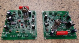
My boards came today. I've got them filled up but my 6.3V transformer hasn't arrived so all I can do is post some pics and wait.
Blessings, Terry
Wow, so many things have happened while I was sleeping 😀
Terry, they look beautiful! Looking forward to see them glowing 😉
I would recommend to test them first without the power section, just to make sure everything is fine (I'm sure it's fine, but you know - some extra care...). For that purpose you will need to connect PD+, ND- and NFB pins together in order to make the VAS cascodes and NFB working properly without the power section.
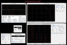
In this configuration you can check the DC offset at the output, see the waves being amplified and make sure there's no oscillation (as usual).
You can also test the power-on sequence options behavior and timing, watching the output with DC-coupled oscilloscope, set in a way that you can see the full range (from "+" rail at the top to "-" rail at the bottom).
Cheers,
Valery
Hi Valery,
Yes,I have tested each IPS first without the OPS attached. I usually attach 470R resistors between PD and ND and the NFB so I can measure the mA of the output. The OPS is set up for 4.5-5mA. That leads me to my first questions for you. This module has no pots. How do you adjust the offset and output? How do you adjust the bias on the vas?
Thanks, Terry
Hi Valery,
Yes,I have tested each IPS first without the OPS attached. I usually attach 470R resistors between PD and ND and the NFB so I can measure the mA of the output. The OPS is set up for 4.5-5mA. That leads me to my first questions for you. This module has no pots. How do you adjust the offset and output? How do you adjust the bias on the vas?
Thanks, Terry
Hi Terry,
Wrote you the answer and then lost it completely somehow 😱
Ok, here is take two 🙂
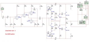
The output of the front end gives 4.5 - 4.7 mA when idle, no adjustment needed normally. If it will still be required - R17 (schematic from post #35) allows adjusting it (lower R - higher output current).
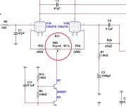
Regarding the DC offset - it is set automatically, assuming the triodes are matched enough within the tube. I have simply selected the tubes with very close parameters for the triodes. In the worst case, it is possible to put a 50 ohm pot between R5 and R8 - see attached picture - it allows adjusting the offset in the range +/- 2V - and then simply measure it and exchange it with 2 normal resistors. Sorry I did not reserve some space for it - just really hoped it would not be required (and in my case it's not).
Cheers,
Valery
Attachments
"Hybrid madness" continues 😉
OK, here is what I came up with so far (next hybrid) - created the new thread - see it HERE. Ideas are welcome. We have to prototype this one - it's going to be a lot of fun - "tubish" sound with low distortion
By the way, we can easily control distortion there - no problem to increase it, just add up to your taste 😀
Output buffer is designed by Damir - I just utilize it here as one of the best ones for the purpose.
Cheers,
Valery
Attachments
Hi Terry,
Wrote you the answer and then lost it completely somehow 😱
Ok, here is take two 🙂
The output of the front end gives 4.5 - 4.7 mA when idle, no adjustment needed normally. If it will still be required - R17 (schematic from post #35) allows adjusting it (lower R - higher output current).
Regarding the DC offset - it is set automatically, assuming the triodes are matched enough within the tube. I have simply selected the tubes with very close parameters for the triodes. In the worst case, it is possible to put a 50 ohm pot between R5 and R8 - see attached picture - it allows adjusting the offset in the range +/- 2V - and then simply measure it and exchange it with 2 normal resistors. Sorry I did not reserve some space for it - just really hoped it would not be required (and in my case it's not).
Cheers,
Valery
Hi Valery,
I have another question if you don't mind. Please keep in mind, I am not questioning your design, I'm trying to learn. You list C16,C17 as 160V. Looks like they only see one rail and go to ground. Why 160V?
Thanks, Terry
Terry, you're right - they only see the rails, so they can be 100V-rated or even 80V-rated easily (though I like to have some safety margin). Sometimes, whem I work on PCB (and re-draw schematic for PCB design purposes), I copy-paste some elements from my previous designs, when I know the physical size is right, even if they are slightly over-rated. This is where 160V came from.
Cheers,
Valery
Cheers,
Valery

Hi Valery,
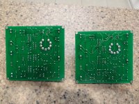
Which files did you use to have your boards made? I sent the ASCII file and the silkscreen is pretty badly offset. It works but it makes it a little more difficult to locate the parts. I am attaching a pic of the boards.
Hi Terry,
I used exactly the P-CAD ASCII file, attached to post #35.
From what I see on your photo, there is some mismatch in silk-screen font (the one pcb manufacturer used for printing the silk-screen) - on your PCB characters are somewhat bigger than expected.
See my PCB attached.
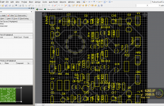
By the way, it is possible to download a free P-CAD viewer HERE - it shows PCB layout from P-CAD ASCII format.
Cheers,
Valery
Attachments
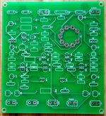
Attached is the picture the board house sent me. I am trying to get to the bottom of it.
Yes, looks a little bit strange - characters are larger than the ones on my PCB and some of them are slightly moved to the left...
Member
Joined 2009
Paid Member
I have known of an issue just like this and in my case it is not produced at the board house. The issue is in a mismatch between what you see on the screen in Eagle edit mode and the creation of the Gerber files (the master images used to manufacture the boards). You should create the Gerber files yourself, then view them carefully with a suitable viewer before you submit them to the board house. The Gerber files will be faithfully reproduced. If you leave the board house to create your Gerber files you can get all sorts of issues. The default in Eagle is to use variable width fonts and these often don't convert well when making Gerbers - at least that is what I have found. So I used fixed width (they are a bit boring!) fonts and then I check the Gerbers - in many cases I still have to adjust the position of text as there is sometimes an offset between what you see in Eagle edit and what shows up on the Gerbers. Check and double check your Gerber files and you'll be fine.
what font did you use for silkscreen ?
looks like boardhouse did font substitution, maybe ?
or just font size difference ?
looks like boardhouse did font substitution, maybe ?
or just font size difference ?
When I first sent the files in to get a quote, I sent both Gerbers and ASCII files for the Low TIM and Valery's Class A. When they sent the quote back they did it based on the ASCII files so when I got ready to order the boards, that is what I sent. I was able to look at the gerbers and they looked right but I couldn't look at the ASCII files. This board house has always sent nice boards before. Now, using the viewer that Valery linked, the screenprint looks fine so I wonder why the board house screen shot looks like what they made.
- Status
- Not open for further replies.
- Home
- Amplifiers
- Solid State
- Low TIM, low distortion hybrid front-end