Well obviously I need to hear more about PIN17 decoupling! 🙂
But first an update; after work I:
- replaced the Jamicon 1000uF tanks with Nippon Chemi-Con AKG 330uF 25v (thinking of hanging a large cap off the P/S, but this amp is only fed >180Hz)
- replaced the big blue 1uF input caps with Russian Military 2.2uF 63v K73-16 PETP
- replaced the small blue "input"(?) caps with Roederstein 2.2uF 63v axial, non-polar "gold"
- replaced two of the blue bootstrap caps with .22uF Kemet monolithic ceramics
- replaced two of the blue bootstrap caps with a parallel configuration of 2x 0.1uF Kemet monolithics + 1x IC 0.01uF "green" ceramics (total ~.21uF, measured higher)
After the initial test quickly revealed a poor solder joint (to my credit) the subsequent listening has been very encouraging. 😀 😱
I was even inspired to play some vinyl - Astrud Gilberto, The Shadow of Your Smile - Verve - Mint copy
Nice work there - glad it worked out. You did a lot of mods so I wonder what the main culprit was. Photos? 🙂
hmm yes, I was reading about this before, but what about this wushuliu's mod then with free pins everywhere?I think it was about decoupling caps. But everything on and off pcb can be an antenna for noise receiving and transmitting. The inputcaps might form a better antenna on YJblue then on other versions, I don't know, there are many loops and half loops on YJblue pcb that might act as antennas too, more then on other pcb's because the loops are larger. But I don't know if lowlevel loss is from these loops/antenna's.

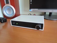
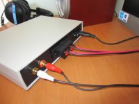
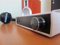
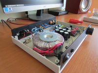
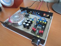
Here is what I came up with.
I'm very pleased with the result. The changes to the board are minor. I replaced the input caps to remove the pop when its turning on.
I'm very pleased with the result. The changes to the board are minor. I replaced the input caps to remove the pop when its turning on.
Attachments

hmm yes, I was reading about this before, but what about this wushuliu's mod then with free pins everywhere?

Or what about the dead bug point-to-point TPA3118D2 amp that I made before any of these Chinese boards were available? It sounds great and did not seem to suffer from antenna pickup issues. Although all components were SMT just wired without a PCB. The foam core substrate had a layer of aluminum foil glued underneath a sheet of paper for a "ground plane" shield. But if you look closely there are high flying wires all over the place and the input caps are quite far from the chip. I think a lot of this discussion of trying to get parts closer and all may be moot. Sure it is important to optimize but listen to an amp that doesn't practice it (like the YJ Blue/black vs YBdz vs DUG's vs deadbug, etc) do you hear a difference? I can't and I can't measure a difference in the system frequency response where it counts - at the listening position with my reference speakers. Maybe we should all not worry so much and just listen to it?
Here is what I came up with.
I'm very pleased with the result. The changes to the board are minor. I replaced the input caps to remove the pop when its turning on.
That's impressive job! 😎
What caps are those?
@xrk971, really cool and a lot of work there 😱
Lowlevel loss is in bootstrap capacitors!!!
Lowlevel loss YJblue was in bootstrap capacitors!!! They carry Epcos logo are blue and do measure 220nF, all 4. I haven't heard it myself yet. 805 ceramics close to chip gave similar results to Rifa MMK in original position. 805 ceramics were removed again and pcbtraces to films tinned (done for 805 originally, they were closer to chip). 805's were tried first and removed again because other objective of the mod was looking if bootstrap capacitor had influence on warming up of 10uH the inductors on YJblue when only power and speakers are connected to YJblue, but input is off, volumepot in minimum position. When YJblue has power but no input, inductors still warm up, with both 805 and rifa films. The idle wave warms the inductors....after 24 hours just power they are close to hot I am told. They seem to warm up less on music, strange... (12-15V PSU)
Lowlevel loss YJblue was in bootstrap capacitors!!! They carry Epcos logo are blue and do measure 220nF, all 4. I haven't heard it myself yet. 805 ceramics close to chip gave similar results to Rifa MMK in original position. 805 ceramics were removed again and pcbtraces to films tinned (done for 805 originally, they were closer to chip). 805's were tried first and removed again because other objective of the mod was looking if bootstrap capacitor had influence on warming up of 10uH the inductors on YJblue when only power and speakers are connected to YJblue, but input is off, volumepot in minimum position. When YJblue has power but no input, inductors still warm up, with both 805 and rifa films. The idle wave warms the inductors....after 24 hours just power they are close to hot I am told. They seem to warm up less on music, strange... (12-15V PSU)
U is an antenna, L is worse antenna, l isn't so much of an antenna (U/L/l as in shape of pcb trace, not letters) (lol so I read, no clue really)
hmm yes, I was reading about this before, but what about this wushuliu's mod then with free pins everywhere?
The bigger the input caps the more risk there is those pick up noise from chip itself and radiate noise. Question was raised here befor, but he did not hear negative effect, or the effect combined with the capacitor sounded better to him. His tuner/cd or whatever he uses didn't stop playing, that does happen sometimes🙂
The big inductors are sold as shielded, so they shouldn't be able to be an antenna???
Lowlevel loss is in bootstrap capacitors!!!
Lowlevel loss YJblue was in bootstrap capacitors!!! They carry Epcos logo are blue and do measure 220nF, all 4. I haven't heard it myself yet. 805 ceramics close to chip gave similar results to Rifa MMK in original position. 805 ceramics were removed again and pcbtraces to films tinned (done for 805 originally, they were closer to chip). 805's were tried first and removed again because other objective of the mod was looking if bootstrap capacitor had influence on warming up of 10uH the inductors on YJblue when only power and speakers are connected to YJblue, but input is off, volumepot in minimum position. When YJblue has power but no input, inductors still warm up, with both 805 and rifa films. The idle wave warms the inductors....after 24 hours just power they are close to hot I am told. They seem to warm up less on music, strange... (12-15V PSU)
Are you saying that the stock blue Epcos bootstrap caps once replaced with ceramics removes the warm inductor problem?! And that warm inductors with no music input is a sign of missing low level info? I do notice that my YJ Blue/black has inductors that are slightly warm to touch but with Ybdz they never get above ambient. The Ybdz uses tantalum "candy drop" style caps on bootstrap and on LC filter. If the coils are warm with no signal it means that there is current flowing back and forth through the coils and this may be sucking up all the low level signal by swamping it with noise that is ultrasonic but eats into the low level SNR nonetheless ?
Illusive,
That is a sweet looking build! Very nice. What voltage is your fancy toroid transformer and cap bank putting out? Also, what value did you end up going with for the input caps? I noticed that your LC filter caps are yellow film 560nJ instead of the TI spec'd 680nJ (same as on mine). I wonder if that is a purposeful switch or did YJ just run out of 680's and thought "close enough"?!

That is a sweet looking build! Very nice. What voltage is your fancy toroid transformer and cap bank putting out? Also, what value did you end up going with for the input caps? I noticed that your LC filter caps are yellow film 560nJ instead of the TI spec'd 680nJ (same as on mine). I wonder if that is a purposeful switch or did YJ just run out of 680's and thought "close enough"?!
Are you saying that the stock blue Epcos bootstrap caps once replaced with ceramics removes the warm inductor problem?! And that warm inductors with no music input is a sign of missing low level info? I do notice that my YJ Blue/black has inductors that are slightly warm to touch but with Ybdz they never get above ambient. The Ybdz uses tantalum "candy drop" style caps on bootstrap and on LC filter. If the coils are warm with no signal it means that there is current flowing back and forth through the coils and this may be sucking up all the low level signal by swamping it with noise that is ultrasonic but eats into the low level SNR nonetheless ?
"When YJblue has power but no input, inductors still warm up, with both 805 and rifa films."
So lowlevel loss isn't related
I actually compared the yellow Thomson 560nF to Wima's on YJblue, the Thomsons sounded better can you believe it🙂 But probably stock blue 680nF run out and these were cheaper I guess🙂
Are those tiny bootstrap smd's tantalum on Wiener? Difficulty comparing Wiener for me is dampening the 22uH filter does on MA speaker, but even so it had more lowlevel then YJblue. The Wiener does have a 6.8uF capacitor on GVDD pin7 too I think: TIdatasheet
Are those tiny bootstrap smd's tantalum on Wiener? Difficulty comparing Wiener for me is dampening the 22uH filter does on MA speaker, but even so it had more lowlevel then YJblue. The Wiener does have a 6.8uF capacitor on GVDD pin7 too I think: TIdatasheet
Internally generated gate voltage supply. Not to be used as a supply or connected to any component other
than a 1 μF X7R ceramic decoupling capacitor and the PLIMIT and GAIN/SLV resistor dividers.
Last edited:
Today I did some quick experiments on th YJ black board:
1.Changed the Jamicons power caps to elma silmic 1000uF standing on the underside of the board. (Very short legs). I hoped it would reduce ringing/sibilance since they would be further from the inductors.
That changed nothing.
2. I added a cheap but large 10uF Mkp cap in parallel to the Silmics. That helped almost nothing.
3.I removed the Silimics and just left the ONE 10uF mkp capacitor. I started to suspect ringing between the 2 powercaps. (Btw, I drive the amp with a laptop powersupply).
I hooked the amp up again 90% of the ringing was gone!!! I then coiled wire from the psu 15 times around a iron bar I had lying around and all the ringing was gone! I have the same ringing on a yj red board too (with a toroid psu) only less ringing. I added a picture whith the solution that sounded great!
Could the ringing/ harsness on these amps be caused by 2 dual power caps?
Attachments
Hi, great build and tidy, where did u get the enclosure, can't find it on ebay?Here is what I came up with.
I'm very pleased with the result. The changes to the board are minor. I replaced the input caps to remove the pop when its turning on.
Today I did some quick experiments on th YJ black board:
1.Changed the Jamicons power caps to elma silmic 1000uF standing on the underside of the board. (Very short legs). I hoped it would reduce ringing/sibilance since they would be further from the inductors.
That changed nothing.
2. I added a cheap but large 10uF Mkp cap in parallel to the Silmics. That helped almost nothing.
3.I removed the Silimics and just left the ONE 10uF mkp capacitor. I started to suspect ringing between the 2 powercaps. (Btw, I drive the amp with a laptop powersupply).
I hooked the amp up again 90% of the ringing was gone!!! I then coiled wire from the psu 15 times around a iron bar I had lying around and all the ringing was gone! I have the same ringing on a yj red board too (with a toroid psu) only less ringing. I added a picture whith the solution that sounded great!
Could the ringing/ harsness on these amps be caused by 2 dual power caps?
TI says in the latest datasheet output will ring if 0.1uF decoupling has bigger distance from chippin then 2.5mm. That chip does have a dac added, only amppart data looks like tpa3118. On YJblue the sometimes harsh sound was lost when 0.1uF's were moved closer to chippins. Now harsh is a observation that will differ from person to person, a peaking outputfilter will sound harsh to some too. When 0.1uF decoupling is moved closer to chippin I could not hear a difference between Elna SilmicII and Panasonic ZA in the other position, I did hear differences between them earlier with 0.1uF in original position. I think it could very well be that now larger value electrolytics will not have trouble they seemed to give earlier. Instead of the 1nF smd I was actually thinking about ~10uF for DUG groupbuy board.
You added a inductor filter to PSU in a inventive way. HF can be injected by PSU, so it is like the pin17 mod, but for both AVCC and PVCC now🙂 Some Japanese and Korean boards have ferrite beads on PSU pcbboard entrance.
My laptop 19v SMPS cable has a ferrite choke right at the input to the amp. I wonder if that type of laptop cable makes a difference. Neat idea to wrap around iron core.
Regarding the dual Silmics causing ringing: I know with dual 470uF or 560uF or 330uF Panasonics - this does not seem to be a problem. The new 330uF 25V Panansonic OSCON SEPF's with very low ESR may be the trick. I wonder if it has to do with low ESR as that absorbs the ringing?
Regarding the dual Silmics causing ringing: I know with dual 470uF or 560uF or 330uF Panasonics - this does not seem to be a problem. The new 330uF 25V Panansonic OSCON SEPF's with very low ESR may be the trick. I wonder if it has to do with low ESR as that absorbs the ringing?
My laptop 19v SMPS cable has a ferrite choke right at the input to the amp. I wonder if that type of laptop cable makes a difference. Neat idea to wrap around iron core.
Regarding the dual Silmics causing ringing: I know with dual 470uF or 560uF or 330uF Panasonics - this does not seem to be a problem. The new 330uF 25V Panansonic OSCON SEPF's with very low ESR may be the trick. I wonder if it has to do with low ESR as that absorbs the ringing?
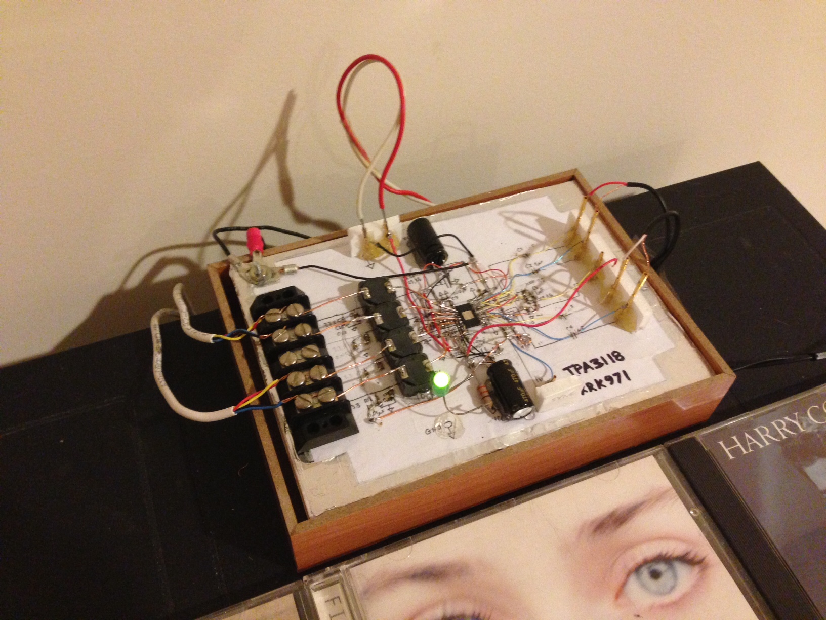
@Irrebeo: so those yellow 560nF caps are Thomsons and they sound better than the blue 680nF's? Well that is great, I will leave them be. The Wiener bootstraps are SMT - see photo. I do not see 6.8uF SMT's on GVdd pin 7?:
Regarding the dual Silmics causing ringing: I know with dual 470uF or 560uF or 330uF Panasonics - this does not seem to be a problem. The new 330uF 25V Panansonic OSCON SEPF's with very low ESR may be the trick. I wonder if it has to do with low ESR as that absorbs the ringing?
@Irrebeo: so those yellow 560nF caps are Thomsons and they sound better than the blue 680nF's? Well that is great, I will leave them be. The Wiener bootstraps are SMT - see photo. I do not see 6.8uF SMT's on GVdd pin 7?:
The laptop powersupply already has a choke on the end but it clearly wasn't enough.. It switches in the audible tweeter frequency too🙁 But it sounded alright with the iron bar mod! Even the audible high pitch disappeared from the psu disappeared. But the harshess doesn't come from the bad psu.. I have the same harsness on the yj red board too, only less of it🙁 If done every mod available to the red board except the 0.1uF decoupling mod. I have changed those out with silmics 2 which helped alot, but still not perfect. For now the black board is clearly best with only upgraded bootstrap caps(smds) and 1 10uF Mkp power cap.
Second smd from left below chip is GVDD pin 7 cap, measures 6.4uF here. I measured other pcb's to see if the 1uFs there measured 1uF, you know I am not very technical, other caps around pin7 could influence value I thought, other pcb's do measure 1uF. So my conclusion is pin7 smd cap is 6.8uF too like the input caps on Wiener. Datasheet says only 1uF should be there, no idea if it makes any difference🙂
Irrebeo,
I did not measure the cap on my board but that cap is supposed to be 1uF (and size appears consistent with that). I think a 6.4uF 25V X7R SMT cap would be much bigger.
Here is datasheet spec:
It may be that when you measure that you are picking up the internal to the 3116 capacitor for its own LDO regulator.
I did not measure the cap on my board but that cap is supposed to be 1uF (and size appears consistent with that). I think a 6.4uF 25V X7R SMT cap would be much bigger.
Here is datasheet spec:
Internally generated gate voltage supply. Not to be used as a supply or connected to any component other
than a 1 µF X7R ceramic decoupling capacitor and the PLIMIT and GAIN/SLV resistor dividers.
It may be that when you measure that you are picking up the internal to the 3116 capacitor for its own LDO regulator.
- Home
- Amplifiers
- Class D
- TPA3116D2 Amp